Honeycomb filter

Active Publication Date: 2008-12-04
NGK INSULATORS LTD
View PDF9 Cites 26 Cited by
  • Summary
  • Abstract
  • Description
  • Claims
  • Application Information

AI Technical Summary

Benefits of technology

[0027]The honeycomb filter of the present invention is constituted so that the exhaust gas which has passed through the first wall portion once flows into the second wall portion having a porosity higher than that of the first and third wall portions and having a porosity of 60% or more. Therefore, the second wall portion functions as a buffer, and the exhaust gas is allowed to pass through the second wall portion so as to apply a more uniform pressure to a broad region of the surface of the third wall portion. In consequence, it can be prevented that the exhaust gas locally flows into the third wall portion, and the pressure loss of the whole honeycomb filter can satisfac

Problems solved by technology

In such a honeycomb filter, the PM is accumulated on the partition walls of the honeycomb structure constituting the filter, whereby a pressure loss rises.
However, during the oxidation and removal of the PM, a fuel is excessively jetted to burn the PM, so that there is a problem that a fuel consumption ratio becomes unfavorable and an economical property deteriorates.
Moreover, the temperature of the honeycomb filter becomes high, so that there is another problem that the honeycomb filter is damaged.
However, in a case where the amount of PM is large, there are problems that the PM is accumulated in layers on

Method used


Image

  • Honeycomb filter
  • Honeycomb filter
  • Honeycomb filter

Examples


example 1

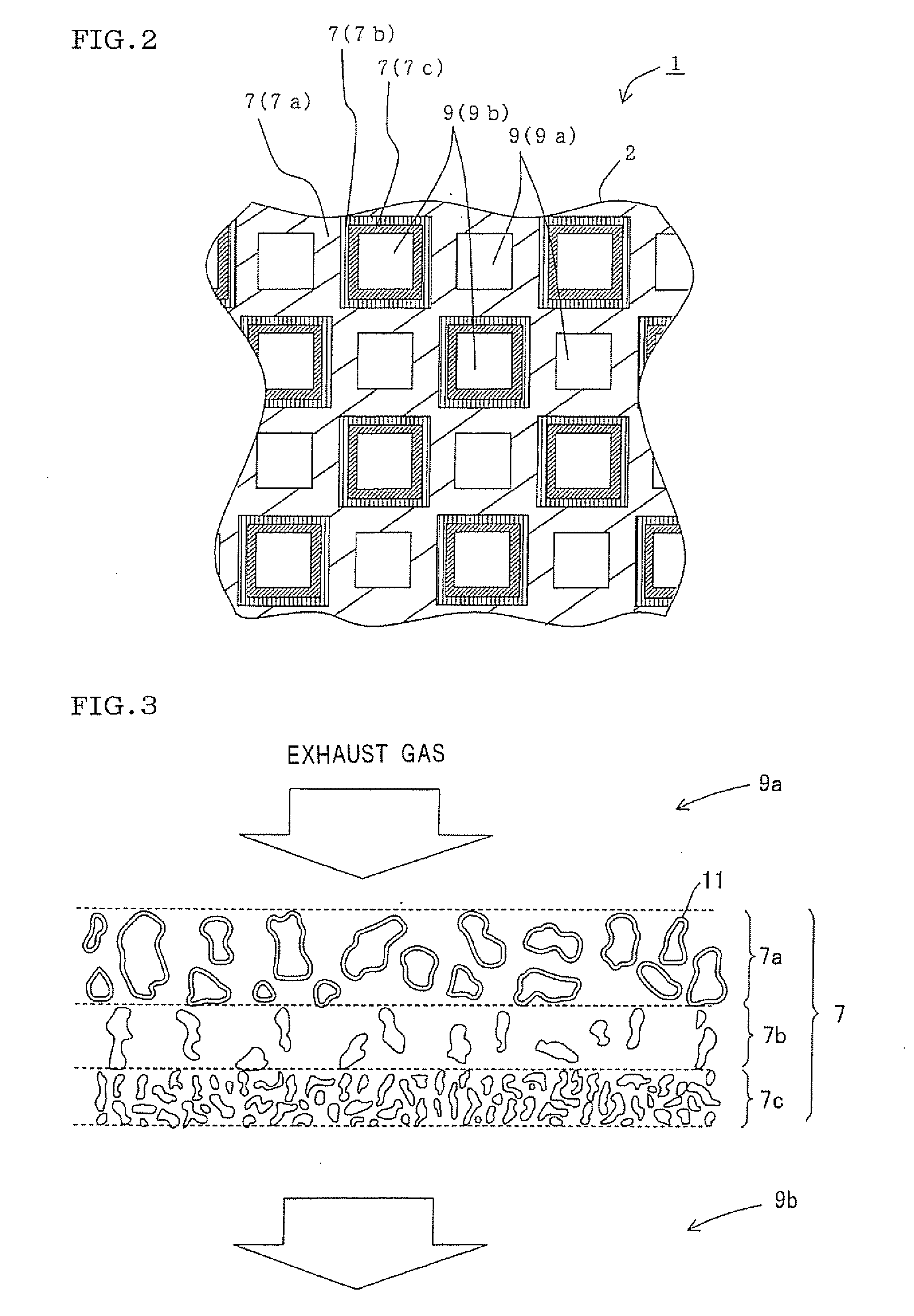
[0172]As a honeycomb filter according to Example 1, as shown in FIG. 13, a honeycomb filter 1 was manufactured in which a portion to be the skeleton of a honeycomb structure 2 was constituted of a third wall portion 7c. A second wall portion 7b and a first wall portion 7a were laminated on the front surface of this third wall portion 7c in the thickness direction of a partition wall 7. Furthermore, a fourth wall portion 7d was arranged on the back surface of the third wall portion 7c.

[0173]First, a forming clay for forming a honeycomb structure precursor made of the third wall portion was prepared. The forming clay was prepared by adding 35 parts by mass of water as a dispersion medium and 5 parts by mass of pore former to 100 parts by mass of cordierite forming material, further adding 6 parts by mass of organic binder and 0.5 part by mass of dispersant, and kneading these materials by use of a kneader. As the cordierite forming material, there was used a heretofore known cordieri...

example 8

[0184]As a honeycomb filter of Example 8, a filter having a honeycomb structure in which a portion to be a skeleton of the honeycomb structure was constituted of a third wall portion, and second and first wall portions were laminated on the front surface of this third wall portion in the thickness direction of a partition wall, was manufactured.

[0185]First, a forming clay for forming a honeycomb structure precursor made of the third wall portion was prepared. The forming clay was prepared by adding 36 parts by mass of water as a dispersion medium and 5 parts by mass of pore former to 100 parts by mass of cordierite forming material, further adding 5 parts by mass of organic binder and 0.5 part by mass of dispersant, and kneading these materials by use of a kneader. As the cordierite forming material, a material constituted in the same manner as in the cordierite forming material used in Example 1 was used.

[0186]Subsequently, the obtained forming clay was extruded using a die having ...

example 9

[0195]A honeycomb filter (Example 9) was manufactured which was constituted in the same manner as in Example 8 except that a slurry containing an aluminosilicate fiber was used as a slurry for a first wall portion, this slurry was atomized with an atomizer and sucked together with air from a masked side to form a layer, and this layer was dried to form the first wall portion. A structure of a honeycomb structure in Example 9 is referred to as a structure C. Table 2 shows the hydraulic diameter of a cell, a PM accumulation time, a PM accumulation pressure loss, a PM trapping efficiency, a detected CO amount, and the evaluation result of general evaluation.


PUM

PropertyMeasurementUnit
Lengthaaaaaaaaaa
Lengthaaaaaaaaaa
Fractionaaaaaaaaaa

Abstract

A honeycomb filter 1 of the present invention includes a honeycomb structure 2 having partition walls 7 and plugging portions, and the partition walls 7 are constituted of a porous layer in which a first wall portion 7a having an average pore diameter of 20 μm or more and carrying an oxidation catalyst 11 on the inner surfaces of formed pores 8, a second wall portion 7b functioning as a buffer and having a high porosity, and a third wall portion 7c having an average pore diameter of 1 to 15 μm and a porosity of 50 to 90% are laminated in the thickness direction of the partition walls 7 from a surface side where cells 9a having opening end portions opened on an inflow side and opening end portions plugged on an outflow side are defined.

Description

TECHNICAL FIELD[0001]The present invention relates to a honeycomb filter. More particularly, it relates to a honeycomb filter capable of realizing a high trapping efficiency and continuously regenerating the filter during the use of the filter, so that a pressure loss can be reduced.BACKGROUND ART[0002]As a dust collecting filter typified by a diesel particulate filter (hereinafter sometimes referred to as the “DPF”), a filter having a honeycomb structure and made of a ceramic (a honeycomb filter) is used.[0003]Usually as the filter for use in such an object, as shown in FIGS. 14 and 15, there is broadly used a wall flow type honeycomb filter 51 having a honeycomb structure 52 in which a plurality of cells 59 communicating between two end faces and constituting fluid passages are partitioned by porous partition walls 57, and plugging portions 58 arranged in checkered patterns complementarily formed by one end face and the other end face of the honeycomb structure 52 so that one of t...

Claims


Application Information

Patent Timeline
IPC IPC(8): B01D53/94
CPCB01D46/2429B01D46/2451B01D46/2466B01D46/247B01D46/2474B01D2046/2433B01D2046/2437B01D2046/2477B01D2046/2481B01D2046/2485B01D2046/2496B01D46/2494B01D46/2488B01D46/249B01D46/24492B01D46/24491B01D46/2498B01D46/2482
Inventor MIZUNO, YUKIOMIYAIRI, YUKIO
Owner NGK INSULATORS LTD
Why Eureka
Try Eureka