Method of manufacturing an optical fiber preform using a high frequency induction thermal plasma

Inactive Publication Date: 2008-12-04
SHIN ETSU CHEM IND CO LTD
View PDF18 Cites 13 Cited by
  • Summary
  • Abstract
  • Description
  • Claims
  • Application Information

AI Technical Summary

Benefits of technology

[0011]It is an object of the present invention to provide a method for manufacturing an optical fiber preform which can suppress the fluctuation of a relative re

Problems solved by technology

As shown in FIG. 2, there exists a problem that the preform produced by the method of FIG. 1 has a fluctuation of a relative refractive-index dif

Method used


Image

  • Method of manufacturing an optical fiber preform using a high frequency induction thermal plasma
  • Method of manufacturing an optical fiber preform using a high frequency induction thermal plasma
  • Method of manufacturing an optical fiber preform using a high frequency induction thermal plasma

Examples


Example

EXAMPLE 1

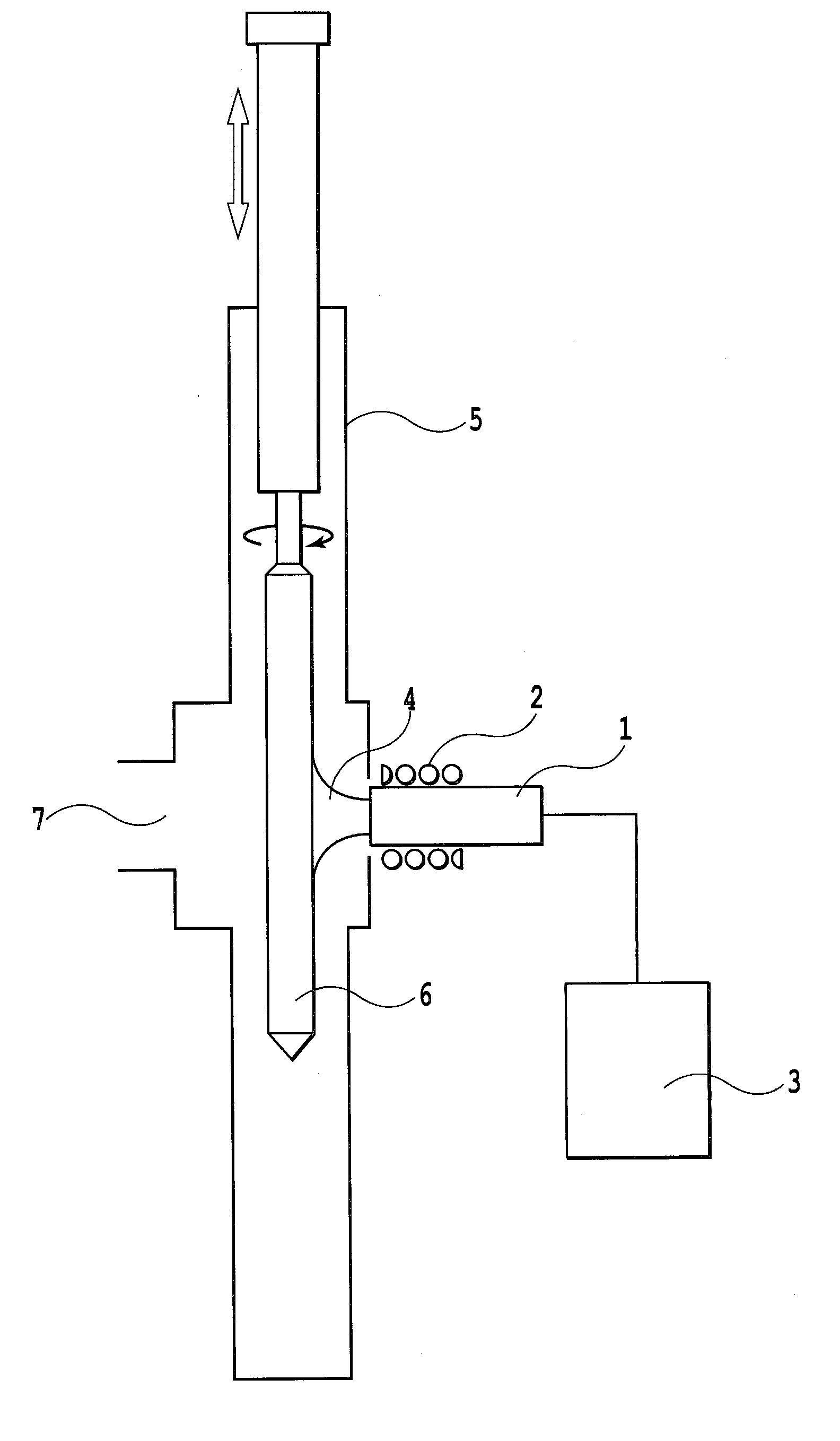
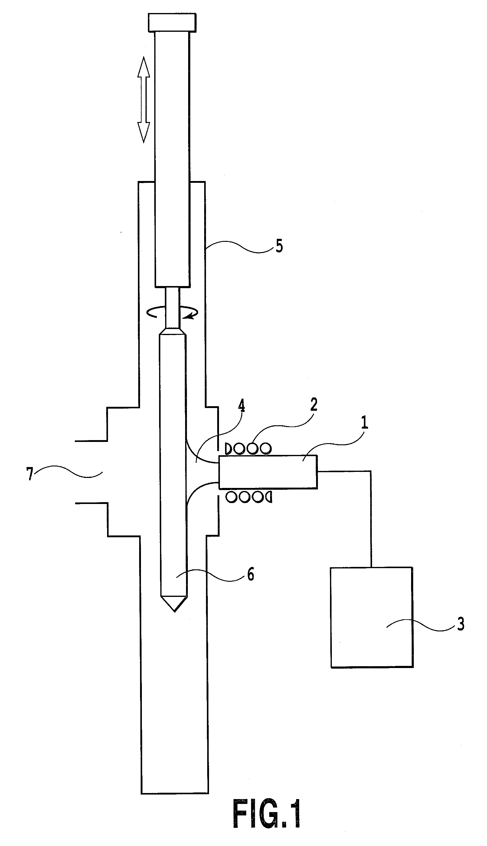
[0037]A fluorine-doped silica glass layer was deposited onto a silica glass rod having a 50 mm outer diameter and a 1100 mm length by using the plasma torch 1. The relative moving speed between the plasma torch 1 and the target 6 in the forward direction was set at 75 mm / min. Silicon tetrachloride and silicon tetrafluoride, as a glass raw material and a source of fluorine, as well as argon and oxygen gases were fed to the plasma torch 1. The electric power to be supplied to the plasma torch 1 was set at 50 kW, which is a lower limit power required for vitrifying the deposited layer.

[0038]The relative moving speed between the plasma torch 1 and the target 6 in the backward direction was set at 500 mm / min. Argon and oxygen gases were fed to the plasma torch, while silicon tetrachloride and silicon tetrafluoride, as a glass raw material and a source of fluorine, were not fed to the plasma torch 1. The electric power to be supplied to the plasma torch 1 was set at 8 kW, which i...

Example

COMPARATIVE EXAMPLE 1

[0040]A fluorine-doped silica glass layer was deposited onto a silica glass rod having a 50 mm outer diameter and a 1100 mm length using a plasma torch 1. The relative moving speed of the target 6 to the plasma torch 1 was set at 75 mm / min in both of the forward and backward directions. Argon gas, oxygen gas, silicon tetrachloride and silicon tetrafluoride were fed to the plasma torch 1. The electric power to be supplied to the plasma torch 1 was set at 53 kW, which is a lower limit power required for transparently vitrifying the deposition layer in the vicinities of the turning positions of the target 6, where the temperature of the target 6 immediately before being subject to the plasma flame 4 becomes lowest in the longitudinal direction of the target 6.

[0041]Under the conditions, the plasma torch 1 was reciprocated 50 times to deposit glass particles onto the target 6 to form a fluorine-doped layer on the target 6. The relative refractive-index difference di...


PUM

PropertyMeasurementUnit
Speedaaaaaaaaaa
Frequencyaaaaaaaaaa
Refractionaaaaaaaaaa

Abstract

When manufacturing an optical fiber preform by feeding at least glass raw material, dopant material and oxygen gas to a high frequency induction thermal plasma torch to synthesize glass particles in plasma therein, a glass rod is rotated and reciprocated relative to the plasma torch to deposit the synthesized glass particles onto the glass rod. The fluctuation of the relative refractive-index difference in the longitudinal direction of the optical fiber preform is suppressed and the average value of the relative refractive-index difference in the longitudinal direction is enhanced. The glass raw material is fed to the plasma torch in a forward direction of the reciprocating motion of the glass rod, and a feeding amount of the glass raw material in the backward direction of the reciprocating motion is reduced relative to the feeding amount in the forward direction.

Description

[0001]This application claims the benefit of Japanese Patent Application No. 2007-142423, filed May 29, 2007, which is hereby incorporated by reference herein in its entirety.BACKGROUND OF THE INVENTION[0002]1. Field of the Invention[0003]The invention relates to a method of manufacturing an optical fiber preform using a high frequency induction thermal plasma.[0004]2. Description of the Related Art[0005]A high frequency induction thermal plasma torch is an apparatus which supplies radio frequency current to a high frequency coil arranged around a gas passage pipe to form a plasma of a gas inside the gas passage pipe so that the plasma is ejected from the torch. This high frequency induction thermal plasma torch allows to obtain an ultra high-temperature plasma gas of about 10,000 degrees C. This plasma gas has relatively low linear velocity and also allows free choice of oxidative or reductive atmosphere, so that it is used as an ultra high-temperature reaction field.[0006]An optic...

Claims


Application Information

Patent Timeline
IPC IPC(8): C03B37/018
CPCC03B37/01413C03B37/01426C03B2207/87C03B2201/12C03B2207/80C03B37/01823Y02P40/57
Inventor OTOSAKA, TETSUYA
Owner SHIN ETSU CHEM IND CO LTD
Why Eureka
Try Eureka