Hydraulic System in Motor Vehicles

a technology of hydraulic system and motor vehicle, which is applied in the direction of clutches, gear lubrication/cooling, clutches, etc., can solve the problems of limiting the hydraulic power output of the oil pump, the cost and complexity the clutch valve, etc., and the cost of complexity is greater. , to achieve the effect of reducing the efficiency reducing the size of the oil pump, and increasing the control cos

Inactive Publication Date: 2008-12-04
ZF FRIEDRICHSHAFEN AG
View PDF3 Cites 18 Cited by
  • Summary
  • Abstract
  • Description
  • Claims
  • Application Information

AI Technical Summary

Benefits of technology

[0012]It should also be pointed out that although in the prior art the cooling of known wet-operating clutches is often designed to be controllable as a function of need, this entails additional control cost and complexity and also influences the size of the oil pumps. To that extent, the efficiency of the oil pumps is reduced because the delivery volume demand for the wet clutch is too large.
[0013]Against this background, the...

Problems solved by technology

In addition, such hydraulic control units often comprise a system-pressure control system as well, which limits the hydraulic power output of the oil pump (in most cases an oversupply to ensure that the maximum demand is covered) in that too much oil is delivered into the intake line of the oil pump or to the oil sump.
For example, if individually controlled clutches are arranged in structural groups of a vehicle, for example in a transfer gearbox which can also be combined with manual shift transmissions and can then not make use of a pressure supply from an automatic transmission, the cost and complexity entailed by the oil pumps, s...

Method used


Image

  • Hydraulic System in Motor Vehicles
  • Hydraulic System in Motor Vehicles
  • Hydraulic System in Motor Vehicles

Examples


Embodiment Construction

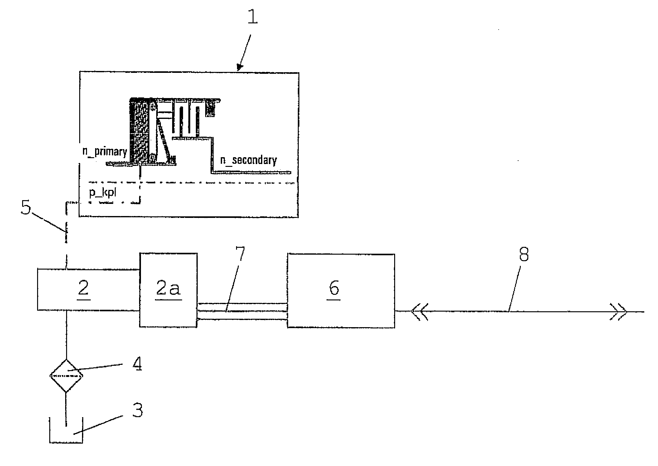
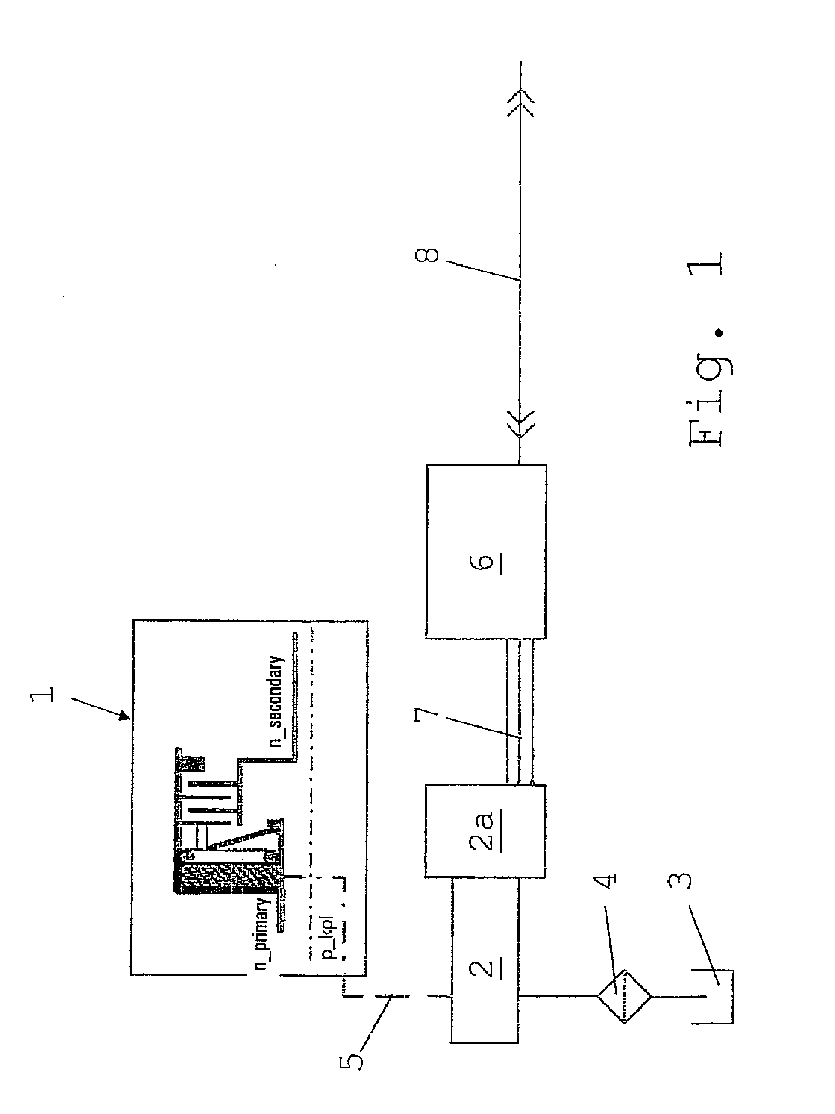
[0033]FIG. 1 is a schematic illustration showing a hydraulically actuated clutch 1, in this case a lamellar or disk clutch of a transmission known in itself (not shown in greater detail), for example a transfer gearbox of a motor vehicle.

[0034]As already explained earlier, the pressure control of the clutch 1 is, in this case, effected directly and exclusively by way of an electrically driven and electronically controlled oil pump 2. The necessary hydraulic oil is drawn from a tank or oil sump 3 and delivered to the clutch 1 as a clutch actuation pressure p_kpl, via a suction filter 4, by the electrically driven oil pump 2 through a pressure line 5.

[0035]The oil pump 2 is associated with an electronic pump control unit 6 which, as a function of clutch pressure specifications and / or clutch torque specifications provided and after evaluating measurement values supplied continuously by an oil pressure sensor (not shown in more detail), generates control signals for controlling an elect...


PUM


Abstract

A hydraulic system in motor vehicles with at least one hydraulically actuated clutch, which entails minimized control complexity for supplying the clutch with hydraulic oil and which takes up less structural space. These characteristics are achieved essentially in that the pressure control of the hydraulically actuated clutch is effected directly and exclusively by an electrically driven and electronically controlled oil pump.

Description

[0001]This application is a national stage completion of PCT / EP2006 / 010981 filed Nov. 16, 2006, which claims priority from German Application Serial No. 10 2005 059 356.9 filed Dec. 13, 2005.FIELD OF THE INVENTION[0002]The invention concerns a hydraulic system in motor vehicles with at least one hydraulically actuated clutch, which is activated by an oil pressure supplied by an oil pump.BACKGROUND OF THE INVENTION[0003]From DE 43 42 233 A1 an oil pump drive device is known, which is combined with a transmission coupled to a drive machine in order to deliver working oil to the transmission for lubrication and to enable shift processes in the transmission. In this, the transmission comprises a first force transfer path to connect the output shaft of an electric motor to the drive input shaft of the oil pump, and a second force transfer path to connect the output shaft of the drive machine to the drive input shaft of the oil pump. A control device selects the first force transfer path ...

Claims


Application Information

Patent Timeline
IPC IPC(8): F16D48/08F16D48/02F16H57/04
CPCF16D25/123F16D48/066F16D2500/1026F16D2500/3024F16D2500/30803F16D2500/70406
Inventor SCHIELE, PETERPOPP, CHRISTIANSCHMIDT, THILO
Owner ZF FRIEDRICHSHAFEN AG
Why Eureka
Try Eureka