Electrophoresis apparatus and pump mechanism used in the same

a technology of electrophoresis apparatus and pump mechanism, which is applied in the direction of laboratory glassware, separation processes, instruments, etc., can solve the problems of deviation of pressure, lower injection pressure, deviation of pressure, etc., and achieve stable pressure, improved processing capacity, and reduced injection time

Active Publication Date: 2008-12-04
HITACHI HIGH-TECH CORP
View PDF3 Cites 6 Cited by
  • Summary
  • Abstract
  • Description
  • Claims
  • Application Information

AI Technical Summary

Benefits of technology

[0015]To raise the processing capacity of an electrophoresis apparatus where a gel or a liquid polymer solution must be injected as a separation medium into capillaries or a capillary array, it is necessary to make the pressure to inject polymer into the capillaries as high as possible. Practically, however, the polymer injection pressure is set lower than the maximum pressure which can be endured by the flow lines of the apparatus. In addition, when the pump pressure may fluctuate due to characteristics of the pump drive system or change with time, the working pressure must be set by taking these factors into consideration so that the pressure never exceeds the maximum allowable pressure of the apparatus. That is, the working pressure must be set lower than the maximum allowable pressure of the flow lines by the possible maximum deviation of the working pressure at least. Thus, a less-deviating pump system can set the working pressure nearer to the maximum pressure endurable by the flow lines and, as a result of the raised working pressure, can advantageously realize an apparatus superior in processing capacity.
[0019]Therefore, it is an object of the present invention to provide an electrophoresis apparatus which is improved in processing capacity by obtaining a stable pressure to inject polymer into the capillary array and consequently reducing the injection time, and it is another object of the present invention to provide a pump mechanism capable of stably generating high discharge pressure.
[0022]An apparatus according to the present invention can provide improved processing capacity by reducing the injection time since it is possible to obtain a stable pressure to fill the capillary array with polymer. Since the plunger is pushed by the action of a spring, it is possible to eliminate the pressure deviation attributable to above-mentioned variations in characteristics among motors.

Problems solved by technology

Practically, however, the polymer injection pressure is set lower than the maximum pressure which can be endured by the flow lines of the apparatus.
These variations in the motor torque characteristics result in a deviation of the pressure.
Further, the frictional force in the lead screw section which converts the motor's rotation to linear motion may change, causing a deviation of the pressure.
Such an adjusting work may deteriorate productivity.
If the change of the load torque is small, pressure control by the above-mentioned method is difficult.

Method used


Image

  • Electrophoresis apparatus and pump mechanism used in the same
  • Electrophoresis apparatus and pump mechanism used in the same
  • Electrophoresis apparatus and pump mechanism used in the same

Examples


embodiment 1

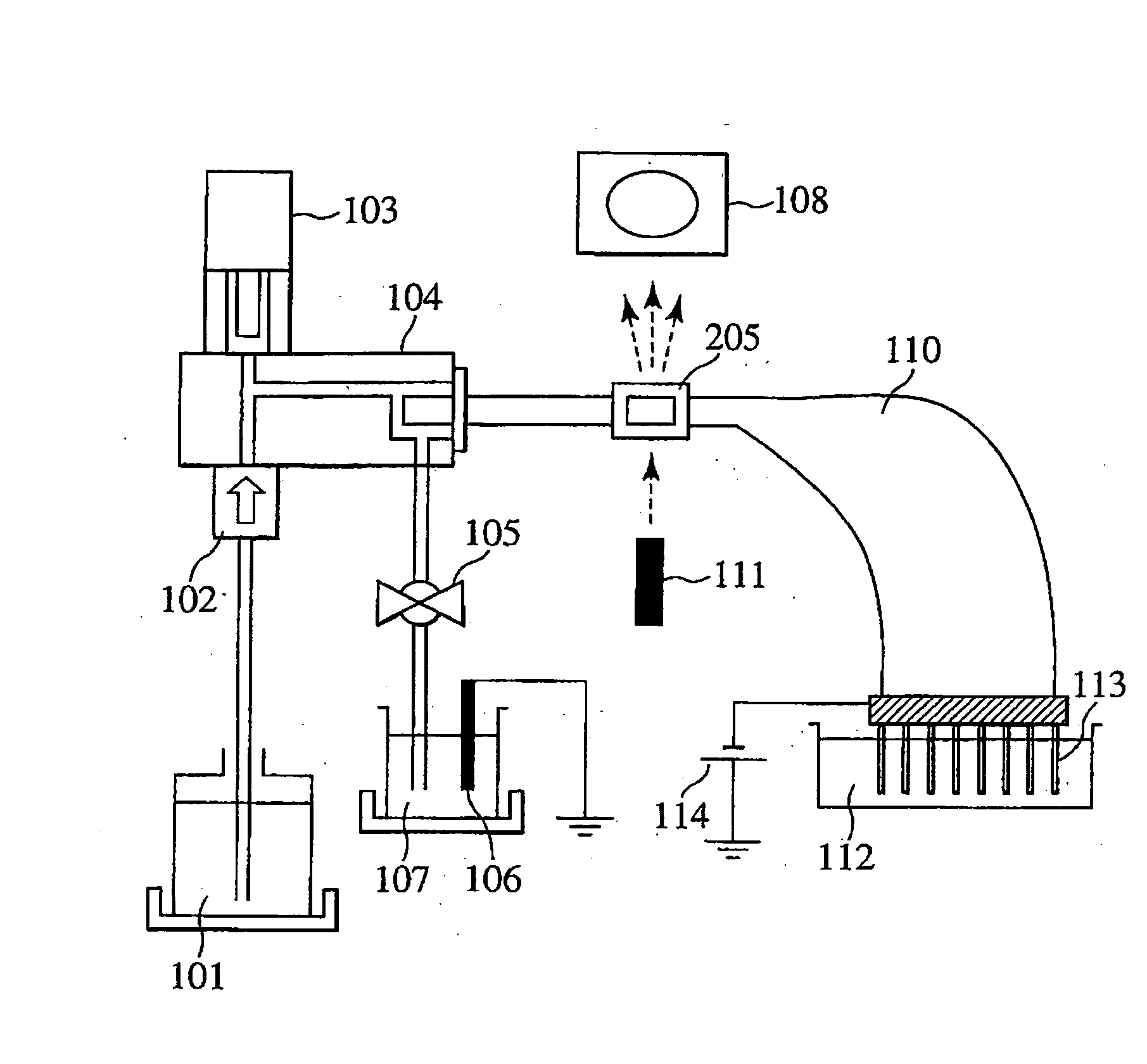
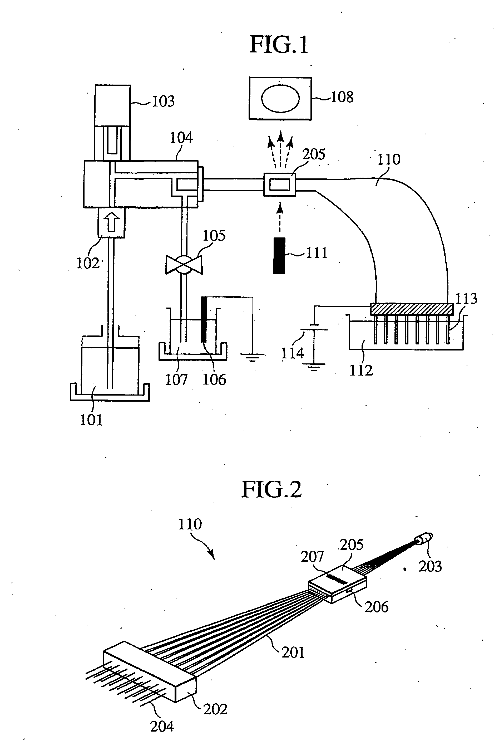
[0043]FIG. 1 schematically shows the basic configuration of a capillary electrophoresis apparatus. The capillary electrophoresis apparatus includes a capillary electrophoresis section and an optical detection section. The capillary electrophoresis section includes capillaries (thin tubes with an internal diameter of several ten to several hundred m) which are filled with an electrophoretic medium, namely a high viscosity polymer solution (hereinafter, referred to as the polymer). The optical detection section detects samples subjected to electrophoresis separation. The capillary electrophoresis apparatus also includes a flow passage block 104 and a polymer injection mechanism. The flow passage block 104 constitutes a junction flow passage which can communicate with the capillaries. The polymer injection mechanism is a pump which can fill the capillaries with the electrophoresis medium. Through operation of the pump 103, the polymer injection mechanism sucks the polymer from a bottle...

embodiment 2

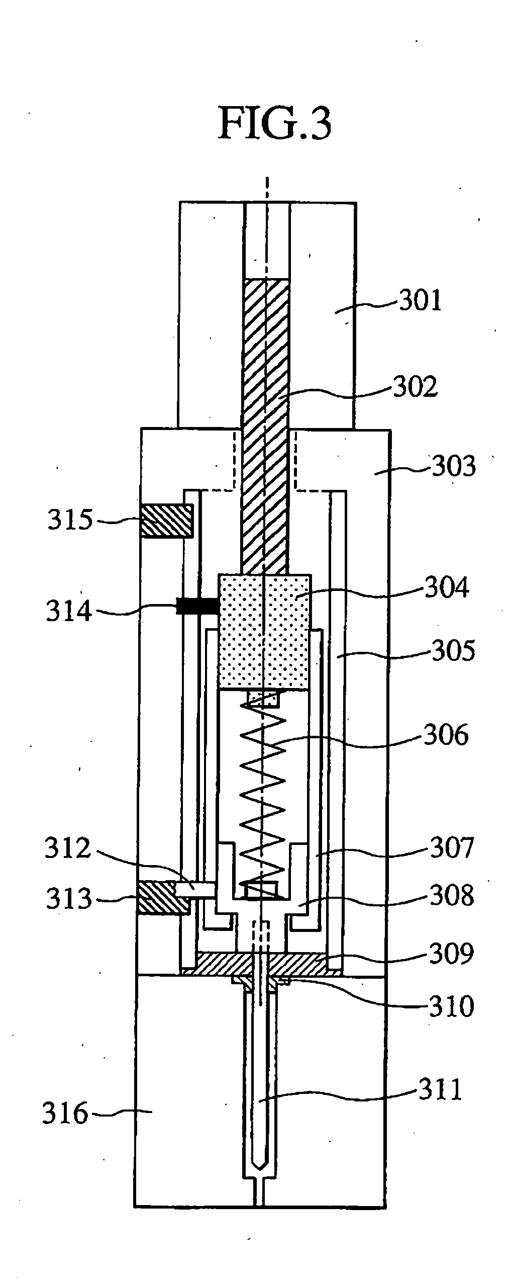
[0066]FIG. 6 schematically shows another plunger drive structure embodiment. Each component identical to the corresponding one in FIG. 3 is given the same reference numeral and description thereof is omitted unless necessary. The present embodiment is different from the aforementioned embodiment 1 in that a slit plate 501 having plural slits, not a detection rod, is attached to the slider 308 and the first sensor 313 is a slit counting encoder 502 attached to the cover 307 not the frame 303. Thus, control is possible to suppress the change of the pressure attributable to characteristics of the spring. This is described below in detail.

[0067]FIGS. 7A to 7C show positional relations between the slider 308 and the cover 307 when polymer is injected in the present embodiment. Initially, polymer is taken in from the polymer bottle through the same procedure as in the first embodiment FIG. 7A. Then, unlike the first embodiment in which the cover 307 is moved to the polymer injection end p...


PUM

PropertyMeasurementUnit
diameteraaaaaaaaaa
inner diameteraaaaaaaaaa

Abstract

To obtain a stable pressure to inject polymer into a capillary array in order to shorten the injection time and raise the processing capacity of the apparatus.Disclosed herein is an electrophoresis apparatus comprising one or more capillaries to be filled with an electrophoretic medium and a pump mechanism which can be connected to the capillaries for filling the capillaries with an electrophoretic medium. The pump mechanism comprises a plunger; a slider which is bonded to the plunger and moves together with the plunger; a spring which gives force to the slider; a cover which limits the range of displacement of the slider; and a linear motion system which is bonded to the cover and moves linearly, wherein the cover and the slider move as one body when the electrophoretic medium is taken to the plunger, and the plunger is pushed by the action of the spring when the electrophoretic medium is injected from the plunger into the capillaries.

Description

BACKGROUND OF THE INVENTION[0001]1. Field of the Invention[0002]The present invention relates to capillary electrophoresis apparatus and pump mechanisms suitable for such electrophoresis apparatus. In particular, the invention relates to an electrophoresis apparatus where a capillary or a capillary array is filled with a gel or a liquid polymer solution which serves as a separating or electrophoretic medium and a pump mechanism suitable for such electrophoresis apparatus.[0003]2. Description of the Related Art[0004]Capillary electrophoresis is in widespread use as a technique to separate / analyze deoxyribonucleic acids (DNAs) and many other biological samples. One of its technical advantages is the superior heat radiation ability due to the capillary's surface area to volume ratio. This heat radiation ability has realized high speed and high resolution separation of analytes by high voltage-used electrophoresis.[0005]Another advantage of the capillary electrophoresis is that analysis...

Claims


Application Information

Patent Timeline
Patent Type & Authority Applications(United States)
IPC IPC(8): G01N27/447
CPCG01N27/44743
Inventor SHOJI, TOMOHIROGOMI, TAKASHI
Owner HITACHI HIGH-TECH CORP
Why Eureka
Try Eureka