Device and method for detecting sulfur dioxide at high temperatures

a high temperature, sulfur dioxide technology, applied in chemical methods analysis, resistance/reactance/impedence, instruments, etc., can solve the problems of increasing the chance that active species can decompose or react with other species, affecting the environment, and affecting the effect of reducing the number of active species

Inactive Publication Date: 2008-12-04
UT BATTELLE LLC
View PDF15 Cites 9 Cited by
  • Summary
  • Abstract
  • Description
  • Claims
  • Application Information

AI Technical Summary

Problems solved by technology

SO2 is harmful to the environment as it produces acid rain when mixed with the water and oxygen present in the earth's atmosphere.
In addition, the time required before the sample can be measured increases the chances that active species can decompose or react with other species.
Furthermore, cooling of the sample causes condensation.
The condensation is problematic because it interferes with the measurement process.
In addition to the difficulties caused by cooling, some of the devices currently used to measure SO2 are not real-time in nature.
The absorption step required by the electrolytic conductivity detector has the disadvantage of increasing the measurement time.
The long sample preparation time is particularly problematic in situations where SO2 is needed to be monitored over time, continuously or in intervals.
The extrapolation can contribute to inaccuracy of the results as well as to an uncertainty of when a certain SO2 level occurred.

Method used


Image

  • Device and method for detecting sulfur dioxide at high temperatures
  • Device and method for detecting sulfur dioxide at high temperatures
  • Device and method for detecting sulfur dioxide at high temperatures

Examples


example 1

Operation of a Three-Electrode Device

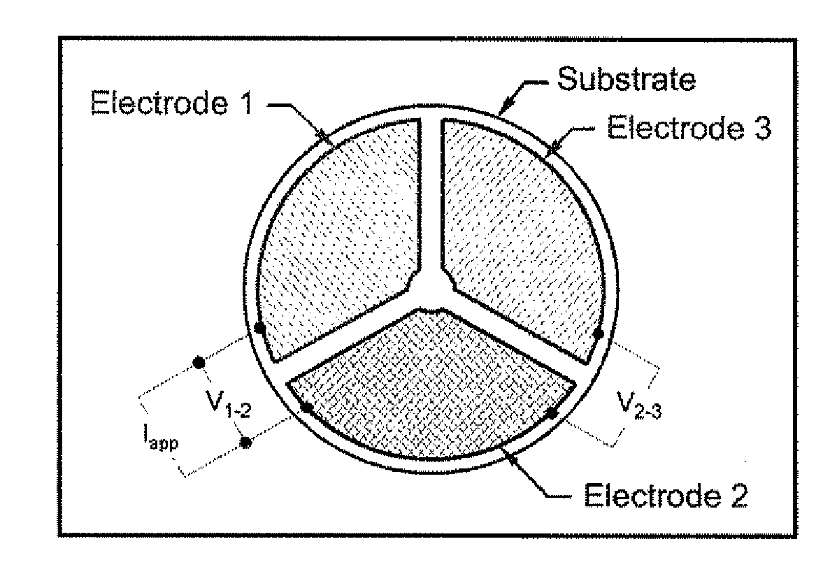
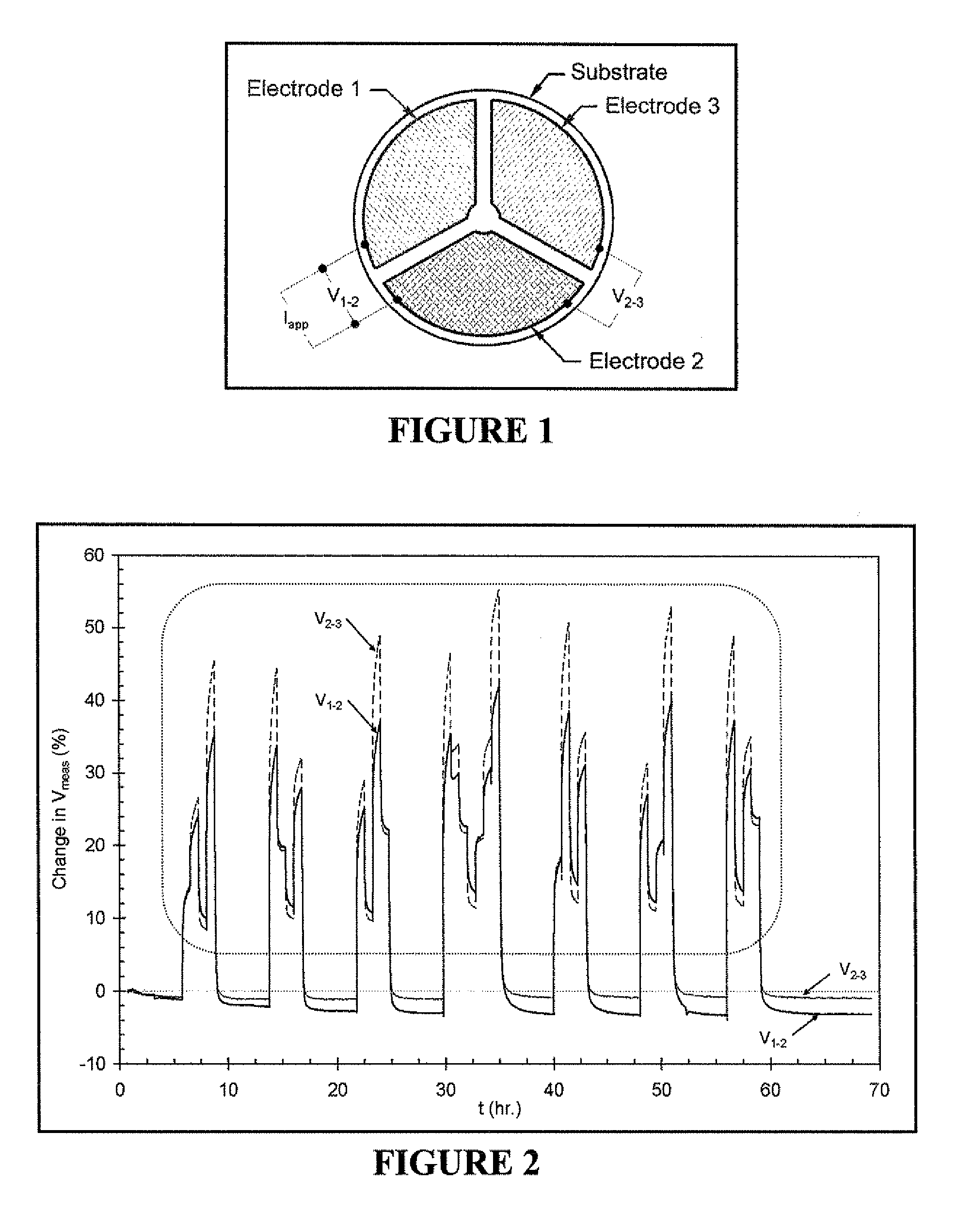
[0122]A preferred embodiment of the invention is shown in FIG. 1. As shown in FIG. 1, this embodiment includes three electrodes, roughly equal in area, on an oxygen ion-conducting substrate. The oxygen ion-conducting substrate has the composition Zr0.84Y0.08O1.92. The composition of electrode 1 is LaCr0.98O3, the composition of electrode 2 is LaCr0.85Mg0.15O3, and the composition of electrode 3 is Pt. The device shown in FIG. 1 was mounted in a fixture that allowed electrical contact (via Pt mesh) to each of the three electrodes and also allowed gas mixtures to be flown directly onto the electroded side of the device. The fixture and device were placed in a resistively heated tube furnace and heated to a temperature of 900° C. A gas mixing unit was then used to supply a mixture of 7 vol % O2, 1.2 vol % H2O (balance N2) to the device. A Keithley 2400 SourceMeter was then used to drive a DC current of 0.125 mA (Iapp in FIG. 1) from electrode 1 to e...

example 2

Effect of Sign and Magnitude of Applied Direct Current

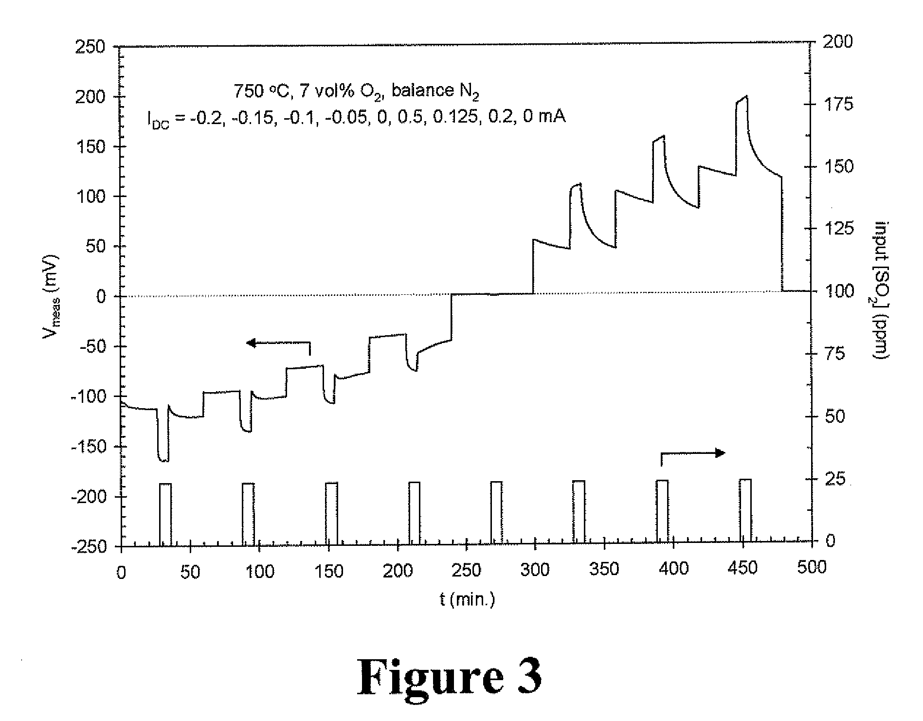
[0125]A device having one electrode made of La0.6Sr0.4Co0.2Fe0.8O3 (electrode 1), one electrode made of LaCr0.85Mg0.15O3 (electrode 2), and one made of Pt (electrode 3) was constructed and operated in accordance with Example 1, except that the operating temperature was 750° C. and no H2O was intentionally added to the gas mixtures. The 2400 SourceMeter of Example 1 was programmed to apply DC currents of −0.2, −0.15, −0.1, −0.05, 0, 0.5, 0.125, 0.2, and 0 mA for periods of one hour each. The gas mixing unit was programmed to supply 25 ppm pulses of SO2 to the device at each of these current settings. The pulses of SO2 were eight minutes in duration and were applied at each current setting after the applied DC current had been constant for 26 minutes.

[0126]The resultant measurements are shown in FIG. 3, which shows V2-3 (the DC voltage between the LaCr0.85Mg0.15O3 and Pt electrodes) as a function of time. For both negative and posi...

example 3

Dependence of Response Magnitude on Concentration of SO2

[0127]The device of Example 2 was subjected to the following measurement procedure: At a temperature of 750° C. and with an O2 concentration ([O2]) of 7 vol %, −0.18 mA was applied between electrodes 1 and 2. [O2] was then changed to 20 vol %, then to 2.4 vol % and held there while the input concentration of SO2 ([SO2]) was varied between 3 and 17 ppm and then set to 0. V2-3 was monitored throughout this series of gas concentration changes and the resultant data are shown in FIG. 4 wherein it is shown that the changes in V2-3 are a single-valued, monotonically increasing function of [SO2] over the range 3-17 ppm. This function furnishes a mathematical relation between the amount of SO2 in the mixture and the changes in V2-3 and thus the measured change in V2-3 can be used to infer the amount of SO2 in a gas mixture containing an unknown amount of SO2. The foregoing shows that the invention is useful for the quantitative detect...


PUM

PropertyMeasurementUnit
temperatureaaaaaaaaaa

Abstract

The present invention relates to a method for selectively detecting and/or measuring gaseous SO2 at a temperature of at least 500° C., the method involving: (i) providing a SO2-detecting device including an oxygen ion-conducting substrate having on its surface at least three electrodes comprising a first, second, and third electrode; (ii) driving a starting current of specified magnitude and temporal variation between the first and second electrodes; (iii) contacting the SO2-detecting device with the SO2-containing sample while maintaining the magnitude and any temporal variation of the starting current, wherein said SO2-containing sample causes a change in the electrical conductance of said device; and (iv) detecting the change in electrical conductance of the device based on measuring an electrical property related to or indicative of the conductance of the device between the first and third electrodes, or between the second and third electrodes, and detecting SO2 in the SO2-containing sample based on the measured change in electrical conductance.

Description

CROSS REFERENCE TO RELATED APPLICATION[0001]This application is claiming benefit from U.S. Provisional Application No. 60 / 914,772 filed on Apr. 30, 2007.[0002]This invention was made with government support under Contract Number DE-AC05-00OR22725 between the United States Department of Energy and UT-Battelle, LLC. The U.S. government has certain rights in this invention.FIELD OF THE INVENTION[0003]The present invention relates to methods and devices for detecting sulfur dioxide (SO2), and more specifically, detecting SO2 at high temperatures of at least 500° C.BACKGROUND OF THE INVENTION[0004]Sulfur dioxide (SO2) is an unwanted by-product of many combustion processes. SO2 is harmful to the environment as it produces acid rain when mixed with the water and oxygen present in the earth's atmosphere. Some of the most widespread sources of SO2 include emissions from diesel engines and electrical power plants run by fossil fuels. Accordingly, there is increasing pressure to regulate and c...

Claims


Application Information

Patent Timeline
Patent Type & Authority Applications(United States)
IPC IPC(8): G01N27/04
CPCG01N27/4074Y10T436/186G01N33/0042Y02A50/20
Inventor WEST, DAVID L.MONTGOMERY, FREDERICK C.ARMSTRONG, TIMOTHY R.
Owner UT BATTELLE LLC
Why Eureka
Try Eureka