Display Capable Electrowetting Light Valve

a technology of electrowetting and display device, which is applied in the direction of diffusing elements, instruments, optics, etc., can solve the problems of high manufacturing process of conventional lcd display panel, large majority of light in a lcd never reaches the viewer, and the inability to meet the requirements of the user, etc., to achieve the highest efficiency operation, high contrast operation, and simple construction

Active Publication Date: 2008-12-04
UNIVERSITY OF CINCINNATI
View PDF6 Cites 212 Cited by
  • Summary
  • Abstract
  • Description
  • Claims
  • Application Information

AI Technical Summary

Benefits of technology

[0010]In one aspect, the display device of the present invention may operate as a high contrast color light valve without use of polarizers, color filters, or view angle enhancing films. In another aspect of the present invention, the display device is capable of more than reflective operation, therefore allowing high contrast operation. In yet another aspect of the present invention, the display device may be manufactured at a fraction of the cost of conventional flat panel display technologies because of its relatively simple construction.
[0011]Another aspect of the present invention is a transflective (a contraction of reflective/transmissive) display that may be viewed in bright ambient lighting or in complete darkness. Another aspect of the present invention is a...

Problems solved by technology

Furthermore, the vast majority (approximately 90 percent or greater) of light in a LCD never reaches the viewer because of unavoidable absorption in thin film polarizers, color filters, and other optical losses in the LCD.
Regardless, even these alternative display technologies have comparable or lower efficiency to that of a LCD display panel.
Moreover, the manufacture processes for conventional LCD's and these conventional alternative flat panel displays...

Method used


Image

  • Display Capable Electrowetting Light Valve
  • Display Capable Electrowetting Light Valve
  • Display Capable Electrowetting Light Valve

Examples


example 1

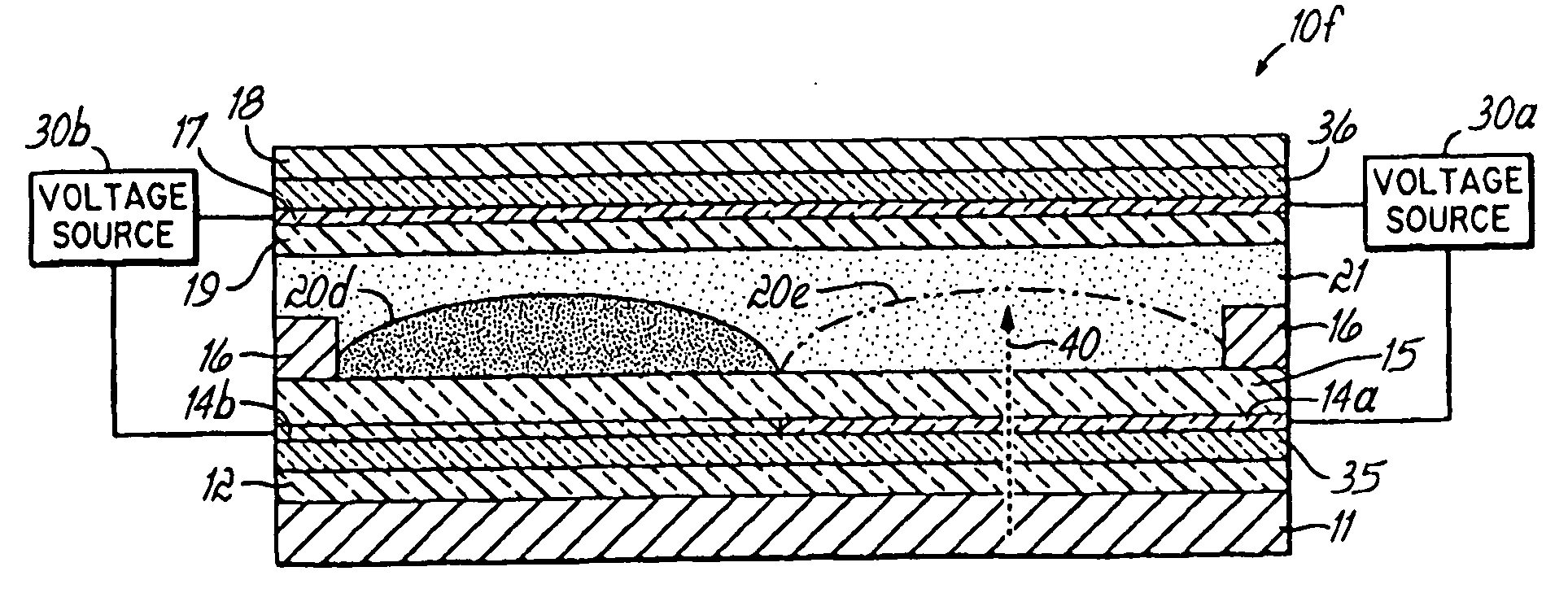
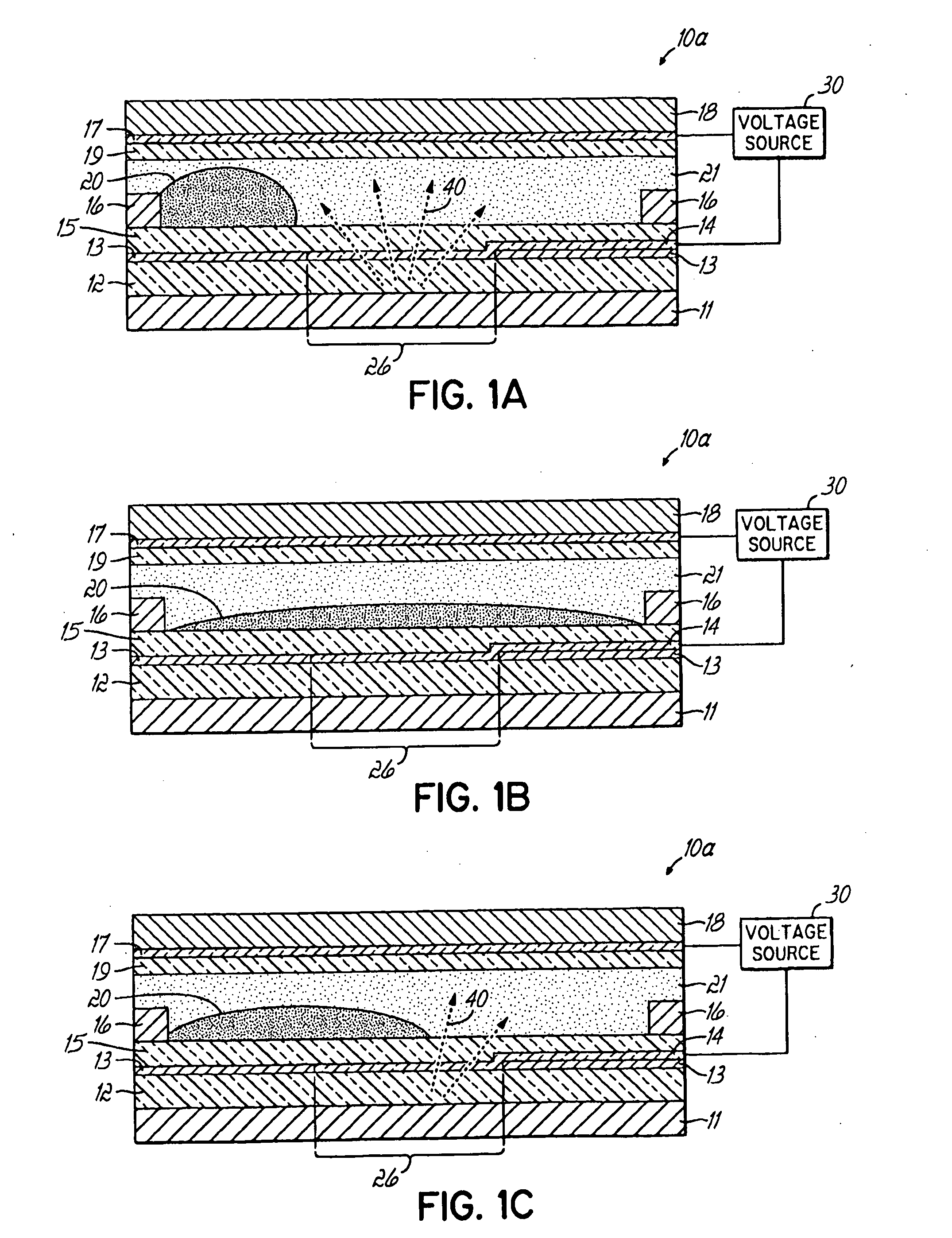
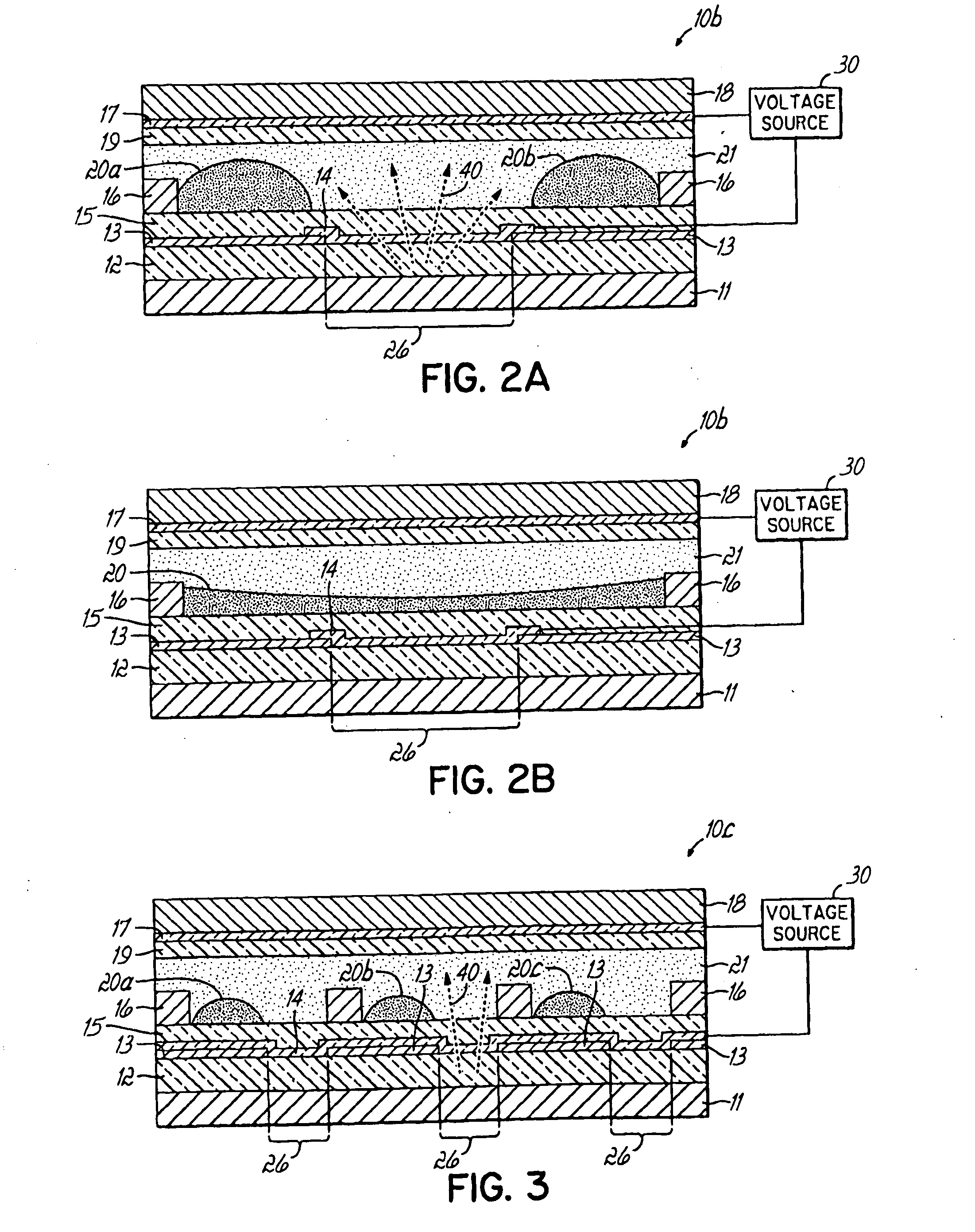
[0074]ELV devices were fabricated on Corning 1737 glass substrates. A lower patterned ground electrode consists of an approximately 50 nm 90% / 10% In2O3 / SnO2 (ITO) film that is transparent (>90%) and electrically conducting (2 in area. A few hundreds of microliters (μL) of deionized water are then dosed over arrays of ELV cells. Next, approximately 10's to approximately 100's nanoliters (nL) of black-dodecane oil is inserted into each ELV cell, forming an oil layer thickness of 10's of μm. The dodecane oil has a surface tension of approximately 25 dynes / cm, causing it to form a continuous film positioned between the water (approximately 73 dynes / cm) and the hydrophobic dielectric (<20 dynes / cm). The oil is further confined laterally by the hydrophilic grid that strongly attracts, and is wetted by, the overlying water layer.

[0075]The oil is rendered opaque through approximately 1 percent by weight (wt. %) doping with red, yellow, and blue colored chromophores. The chromophores are non...

example 2

[0077]The ELV devices of Example 1 were modified by inclusion of an Al reflector with an aperture placed between the glass substrate and transparent electrode. The ELV devices were tested and found to exhibit 60:1 ON / OFF contrast, 10 ms switching speed, and a maximum of 85% transmission.

example 3

[0078]The ELV devices of Example 1 were modified by inclusion of a diffusely reflecting and partially transmitting DuPont Luxprint™ dielectric between the hydrophobic dielectric and the transparent electrode. The ELV devices were tested and found to be legible in both dark lighting due the backlight and in 100,000 lux bright sunlight due to reflection from the partially reflective diffuse dielectric.


PUM


Abstract

The invention relates to light transmissive, transflective, or reflective flat panel display devices and, more specifically, to light emissive flat panel displays constructed from high performance electrowetting light valve (ELV) devices (10a-g). An array of ELV devices (10a-g) is mounted on or adjacent to a backlight (11), employing a reflector (13) allowing for improved transmission. The backlight (11) may be partially diffusely reflective or translucent as to also allow for creation of a transflective display panel.

Description

CROSS-REFERENCE TO RELATED APPLICATIONS[0001]This application claims the benefit of U.S. Provisional Application No. 60 / 586,555, filed on Jul. 9, 2004, the disclosure of which is hereby incorporated by reference herein in its entirety.FIELD OF THE INVENTION[0002]The present invention relates to flat panel display devices and, more specifically, to flat panel display devices that incorporate a high performance electrowetting light valve structure.BACKGROUND OF THE INVENTION[0003]Many technologies are currently being developed to provide the next generation of flat panel displays, projection displays, flexible displays, and micro-displays. Consumers consider flat-panel emissive displays, which emit light in a lambertian behavior, to be the most attractive type of display. Despite the human eye's natural affinity for such emissive displays, liquid crystal displays (LCD's) currently dominate the commercial display market. Because LCD's filter white light, which passes through polarizers...

Claims


Application Information

Patent Timeline
IPC IPC(8): G02F1/00
CPCG02B5/02G02B26/004
Inventor STECKL, ANDREW J.HEIKENFELD, JASON C.
Owner UNIVERSITY OF CINCINNATI
Why Eureka
Try Eureka