Wastegate assembly

a wastegate and assembly technology, applied in the direction of machines/engines, liquid fuel engines, forging/pressing/hammering apparatus, etc., can solve the problems of unreliable valve assemblies, noise and vibration of turbochargers, and propensity for seizing in the closed position, so as to facilitate the manufacturing process, cost-effective and reliable

Active Publication Date: 2008-12-04
BORGWARNER INC
View PDF4 Cites 37 Cited by
  • Summary
  • Abstract
  • Description
  • Claims
  • Application Information

AI Technical Summary

Benefits of technology

[0011]The exemplary embodiment of the wastegate assembly, and the turbocharger that uses the assembly, allows for pre-assembly and/or pre-calibration. The exemplary embodiment of the

Problems solved by technology

Additionally, due to the resulting high velocity of flow, turbochargers are subjected to noise and vibration.
Such conditions can have a detrimental effect on the components of the turbocharger, particularly on the rotating parts such as the turbine rotor, which can lead to failure of the system.
These valve assemblies have been shown to be u

Method used


Image

  • Wastegate assembly
  • Wastegate assembly
  • Wastegate assembly

Examples


Embodiment Construction

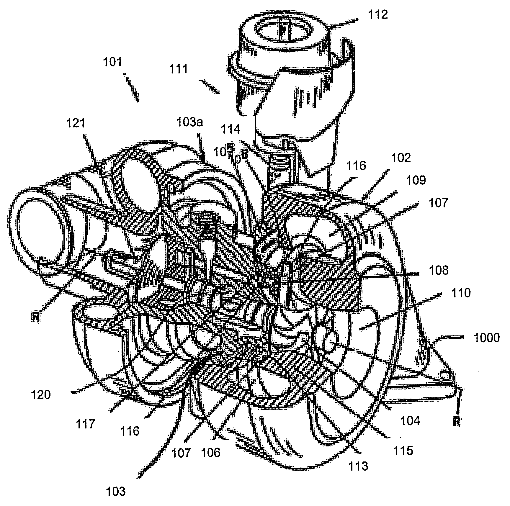
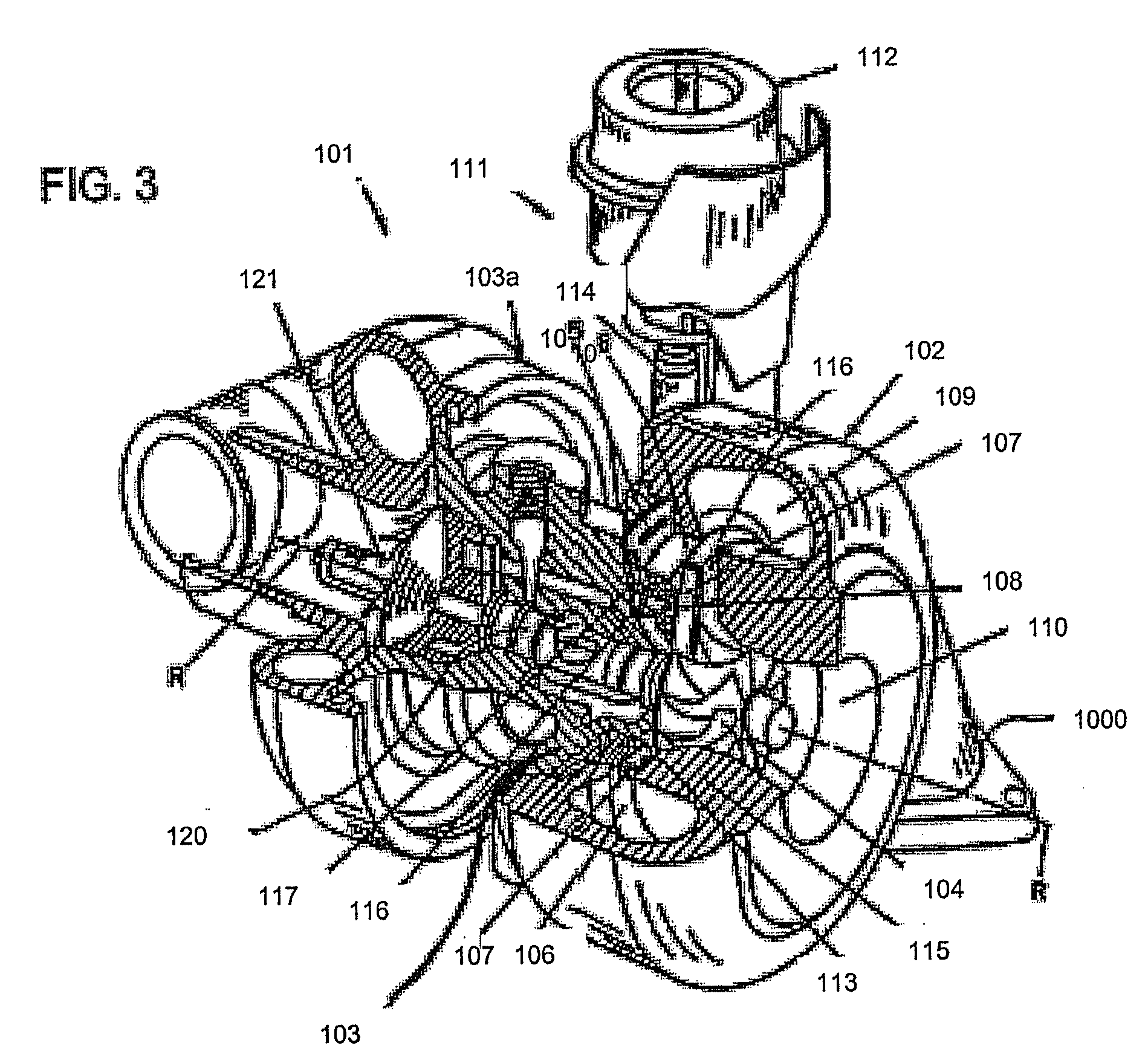
[0025]Referring to FIG. 3, a turbocharger 101 has a turbine housing 102, a center housing 103 and a compressor housing 103a connected to each other and positioned along an axis of rotation R. The turbine housing 102 has an outer guiding grid of guide vanes 107 over the circumference of a support ring 106. The guide vanes 107 may be pivoted by pivoting shafts 108 inserted into bores of the support ring 106 so that each pair of vanes define nozzles of selectively variable cross-section according to the pivoting position of the vanes 107. This allows for a larger or smaller amount of exhaust gases to be supplied to a turbine rotor 104.

[0026]The exhaust gases are provided to the guide vanes 107 and rotor 104 by a supply channel 109 having an inlet 1000. The exhaust gases are discharged through a central short feed pipe 110, and the rotor 104 drives the compressor wheel, impeller or rotor 121 fastened to the shaft 120 of the wheel. The present disclosure also contemplates one or more of ...


PUM

PropertyMeasurementUnit
Angleaaaaaaaaaa
Shapeaaaaaaaaaa

Abstract

A wastegate assembly (200) for a turbocharger (101) or the like is provided having a support plate (300), an actuator (275), a linkage (250) operably connected to the actuator (275), and a valve plate (225) operably connected to the linkage (250). The linkage (250) translates actuation of the actuator (275) to movement of the valve plate (225) thereby sealing or unsealing the bypass outlet (500). The actuator (275), linkage (250) and valve plate (225) can be pre-assembled to the support plate (300) prior to the support plate (300) being connected to the turbine housing (102). The actuator (275), linkage (250) and valve plate (225) can be calibrated prior to the wastegate assembly (200) being connected to the turbine housing (102). The bypass outlet (500) can be machined via access provided by the wastegate port (400).

Description

CROSS REFERENCE TO RELATED APPLICATIONS[0001]This application is related to and claims priority in, copending U.S. Provisional Application Ser. No. 60 / 893,281, filed Mar. 6, 2007, the disclosures of which are incorporated herein by reference.FIELD OF THE INVENTION[0002]This invention is directed to a turbocharging system for an internal combustion engine and more particularly to a turbine housing having a wastegate.BACKGROUND OF THE INVENTION[0003]Turbochargers are a type of forced induction system. They compress the air flowing into an engine, thus boosting the engine's horsepower without significantly increasing weight. Turbochargers use the exhaust flow from the engine to spin a turbine, which in turn drives an air compressor. Since the turbine spins about 30 times faster than most car engines and it is hooked up to the exhaust, the temperature in the turbine is very high. Additionally, due to the resulting high velocity of flow, turbochargers are subjected to noise and vibration...

Claims


Application Information

Patent Timeline
IPC IPC(8): F04D27/00B23P15/00
CPCF02B37/186F05B2220/40Y10T29/49236Y10T29/4932Y10T29/49995Y02T10/144Y02T10/12
Inventor HARRIS, MICHAEL E.
Owner BORGWARNER INC
Why Eureka
Try Eureka