
Method of Scribing and Breaking Substrate Made of a Brittle Material and System for Scribing and Breaking Substrate

a technology of brittle material and substrate, which is applied in the direction of conveyors, manufacturing tools, instruments, etc., can solve the problem of easy generation of substrate damag

Inactive Publication Date: 2008-12-11
MITSUBOSHI DIAMOND IND CO LTD
View PDF3 Cites 38 Cited by
  • Summary
  • Abstract
  • Description
  • Claims
  • Application Information

AI Technical Summary

Benefits of technology

The present invention relates to a method and system for scribing and breaking a substrate made of a brittle material, such as glass or ceramics, using a laser beam. The invention addresses the problem of generating defects and cracks when using a cutter wheel to form scribed lines and then breaking the substrate along the lines. The invention provides a method and system for forming vertical cracks in a substrate, which allows for easier and more complete breaking of the substrate. The method involves heating the substrate with a laser beam to form a trigger crack, and then using the laser beam to create a vertical crack that intersects with the trigger crack. This allows for a smooth transition of the substrate from the cutter wheel process to the breaking process, and maintains the strength of the substrate. The invention also addresses the problem of generating defects when breaking the substrate along the scribed lines, and provides a method for forming vertical cracks along the lines to prevent such defects.

Problems solved by technology

Usually, when a substrate made of a brittle material is scribed with a cutter wheel, defect of the substrate tends to generate easily due to a mechanical stress applied to the substrate by the cutter wheel, and crack or the like is generated due to the above-mentioned defect when breaking is carried out.

Method used


Image

  • Method of Scribing and Breaking Substrate Made of a Brittle Material and System for Scribing and Breaking Substrate
  • Method of Scribing and Breaking Substrate Made of a Brittle Material and System for Scribing and Breaking Substrate
  • Method of Scribing and Breaking Substrate Made of a Brittle Material and System for Scribing and Breaking Substrate

Examples


Embodiment Construction

[0096]Hereinafter the method of scribing and breaking a substrate made of a brittle material and the system for putting this method into practice will be described with referent to the accompanying drawings.

[0097](Apparatus Composition)

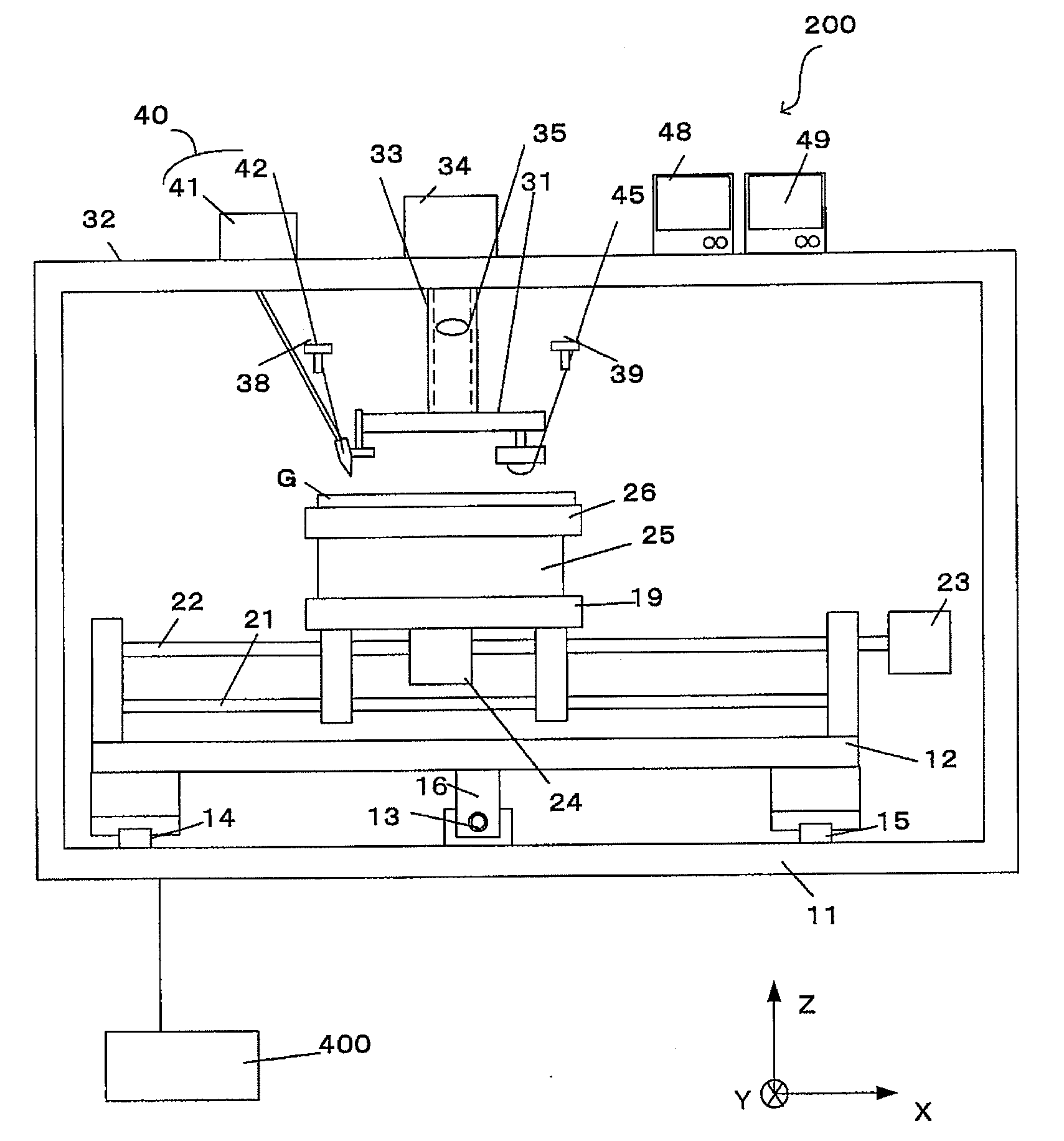
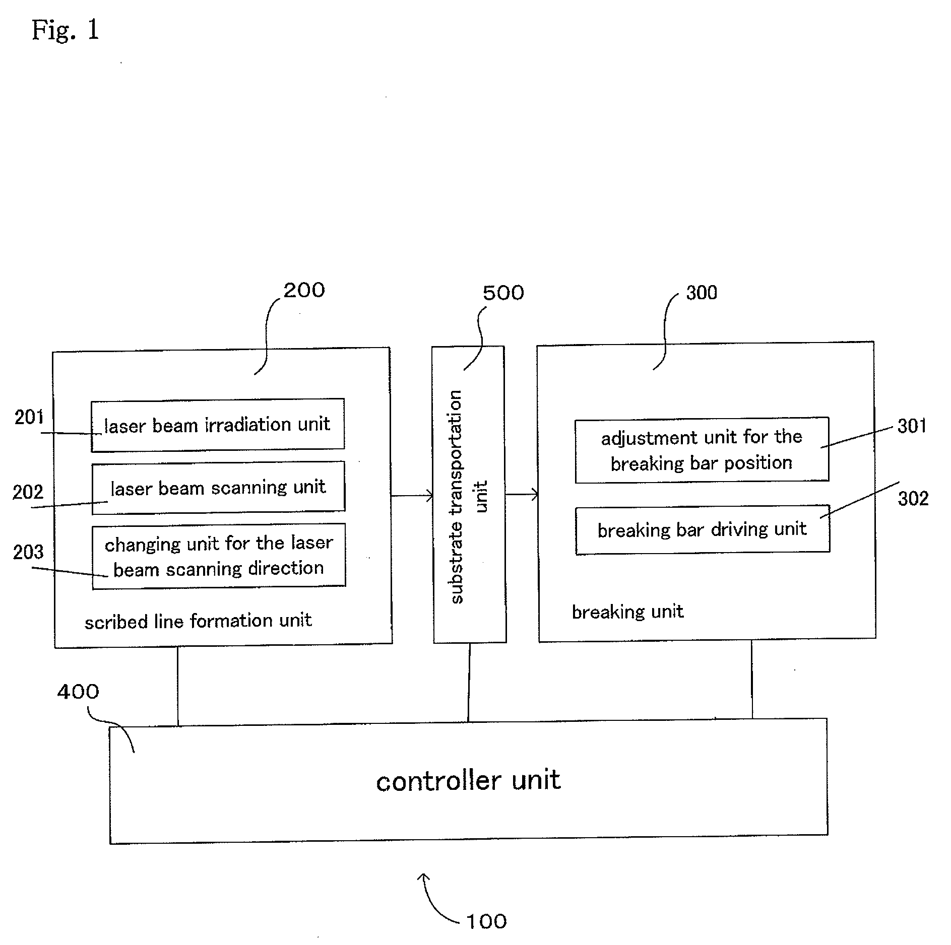
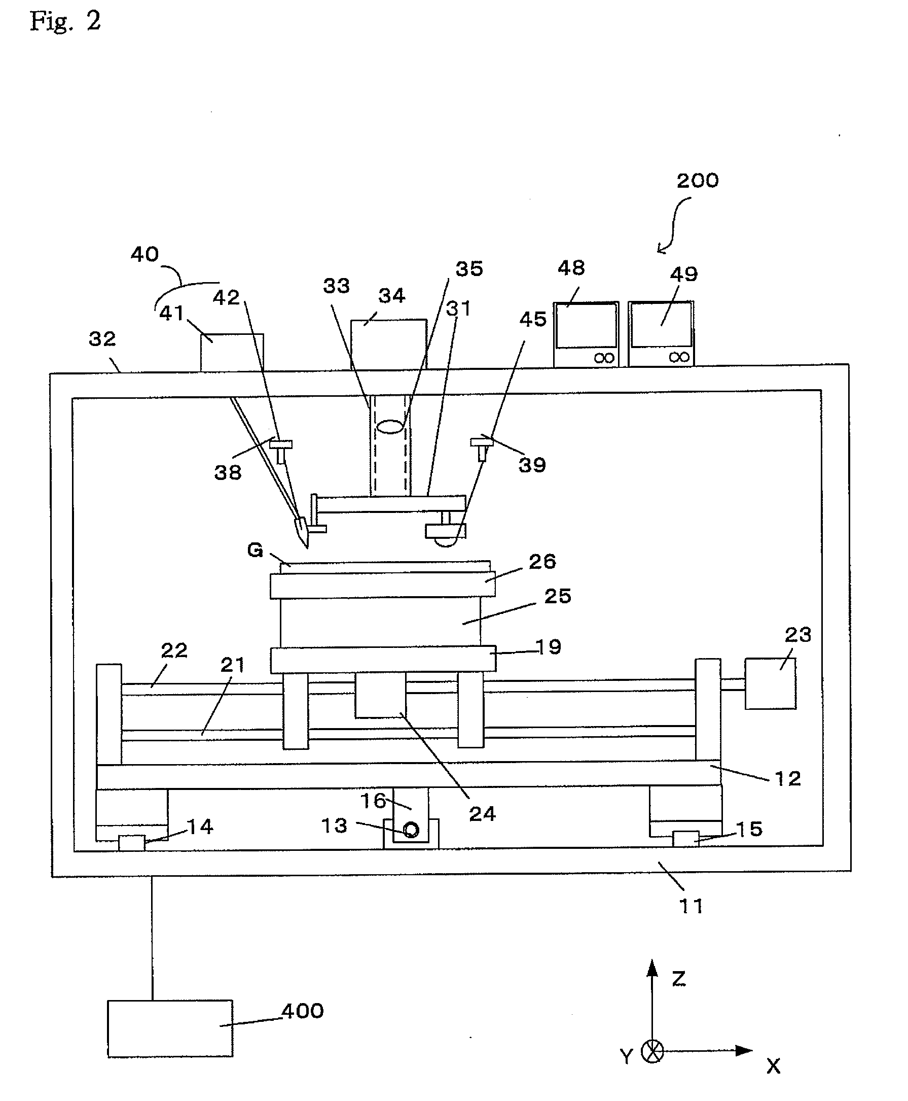
[0098]FIG. 1 is the block schematic diagram illustrating a system 100 for scribing and breaking a substrate, one embodiment to be used according to the present invention. The scribing and breaking system 100 thereof constitutes a scribing unit 200, a breaking unit 300 and a controller unit 400 controlling them in whole. The scribing unit 200 and the breaking unit 300 can be unified to be an integral structure, but in this working example the two units are separated. Accordingly, there is a substrate transportation unit 500 of widely known robot type between them. By means of a controller unit 400 transportation and inversion of substrates can be carried out from the scribing unit 200 to the breaking unit 300.

[0099]The scribing unit 200 works in the sa...


PUM

PropertyMeasurementUnit
energy densityaaaaaaaaaa
thicknessaaaaaaaaaa
melting temperatureaaaaaaaaaa

Abstract

An object of the present invention is to provide a method of scribing and breaking a substrate made of a brittle material by which good-quality cutting surface of the substrate can be obtained without any defects such as chippings on the substrate.The method comprises (a) the first scribing step in the first direction by controlling the relative moving velocity and output power of the laser beam so that local volume shrinkage and local tensile stress can be generated in the vicinity of the formed first scribed line, (b) the second scribing step in the second direction of forming locally trigger cracks, which use tensile stress in the vicinity of the first scribed line and work as a starting point in the second direction, in the vicinity of the intersection of a scribed line in the first direction with a scribed line in the second direction, (c) the first breaking step of breaking the substrate along the first scribed line in the first direction, and (d) the second breaking step of breaking the substrate along the second scribed line in the second direction after the first breaking step and performing the breaking from the trigger that works as a starting point of breaking.

Description

FIELD OF THE INVENTION[0001]The present invention relates to a method of scribing and breaking a substrate made of a brittle material and a system for scribing and breaking a substrate, wherein a mother substrate made of a brittle material such as glass, ceramics of sintered material, single crystal silicon, sapphire, semiconductor wafer, or ceramics substrate, is scribed and broken after heated lower than a melting temperature by using a laser beam to form a scribed line with a vertical crack, and particularly, relates to a method of scribing and breaking a substrate made of a brittle material and a system for scribing and breaking a substrate, wherein vertical cracks in two directions intersecting each other are formed in a substrate made of a brittle material, and then the substrate is broken along the two directions.BACKGROUND OF THE ART[0002]Usually, a cutter wheel is pressed against a substrate of a brittle material and moved with rotation to form a scribed line, and the subst...

Claims


Application Information

Patent Timeline
Patent Type & Authority Applications(United States)
IPC IPC(8): H01L21/301B23K26/00B23K26/364B23K101/40B28D5/00C03B33/09G02F1/13G02F1/1333
CPCB23K26/4075B28D5/0011B65G2249/04C03B33/0222C03B33/033C03B33/091C03B33/093H01L21/67092H01L21/67282H05K1/0306H05K3/0029H05K3/0052H05K2201/09036H05K2201/0909H05K2203/302B23K26/40B23K2103/50Y02P40/57B23K26/38H01L21/30
Inventor UENO, TSUTOMUOTODA, KENJIYAMAMOTO, KOJI
Owner MITSUBOSHI DIAMOND IND CO LTD
Learn More