[0022]With the configuration of the preferred embodiment, when the engine is provided with the NOx concentration-detecting means for outputting a
signal indicative of the concentration of NOx in exhaust gases, and the reducing agent concentration-detecting means for outputting a
signal indicative of the concentration of the reducing agent in exhaust gases, it is possible to obtain the same advantageous effects described above.
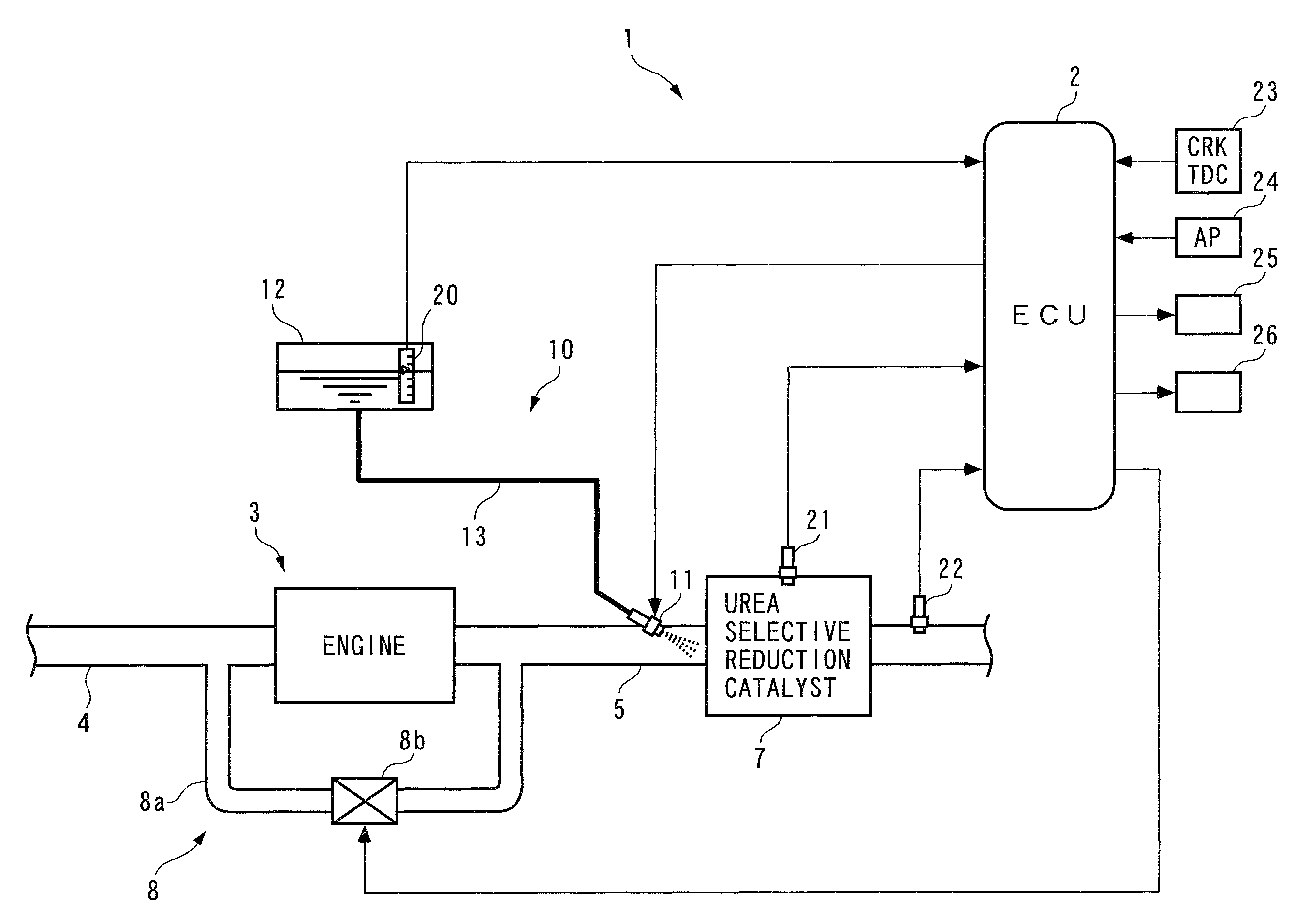
[0023]To attain the above object, in a second aspect of the present invention, there is provided an exhaust emission control device for an internal
combustion engine, comprising a selective reduction catalyst disposed in an exhaust passage of the engine, for purifying NOx in exhaust gases flowing through the exhaust passage, in the presence of a reducing agent,
exhaust gas concentration-detecting means disposed in the exhaust passage at a location downstream of the selective reduction catalyst, for outputting a detection signal indicative of concentrations of predetermined components including NOx in exhaust gases, a reducing agent supply device for supplying the reducing agent to the selective reduction catalyst, NOx purification ratio parameter-calculating means for calculating a NOx purification ratio parameter having a correlation with a NOx purification ratio of the selective reduction catalyst, NOx purification ratio-calculating means for calculating the NOx purification ratio, based on the NOx purification ratio parameter, by using a correlation model defining a correlation between the NOx purification ratio parameter and the NOx purification ratio of the selective reduction catalyst degraded to a predetermined degree of degradation, supply amount-determining means for determining an amount of supply of the reducing agent to the selective reduction catalyst by the reducing agent supply device, according to the NOx purification ratio, and supply amount-correcting means for calculating a supply amount correction value according to a value of the detection signal from the
exhaust gas concentration-detecting means, and correcting the amount of supply of the reducing agent to the selective reduction catalyst, by using the supply amount correction value, wherein the NOx purification ratio-calculating means comprises
model modification value-calculating means for calculating a
model modification value with a predetermined
algorithm such that an absolute value of the supply amount correction value is reduced, and purification ratio-calculating means for calculating the NOx purification ratio by using the correlation model modified by the
model modification value.
[0024]With the configuration of the
control system according to the second aspect of the present invention, the NOx purification ratio is calculated based on the NOx purification ratio parameter, using the correlation model that defines the relation between the NOx purification ratio parameter and the NOx purification ratio of the selective reduction catalyst in a state degraded to a predetermined degradation degree (e.g. in a new condition, and hence degradation degree=0), and according to the calculated NOx purification ratio, the amount of supply of the reducing agent to the selective reduction catalyst by the reducing agent supply device is determined. Further, the supply amount correction value is calculated based on the value of the detection signal from the exhaust
gas concentration-detecting means, and the amount of the reducing agent is corrected using the supply amount correction value. As described above, when the supply amount of the reducing agent is controlled while being corrected using the supply amount correction value, since the supply amount correction value is calculated based on the value of the detection signal, there is a fear that
response delay is caused before the results of correction of the supply amount of the reducing agent are reflected on the value of the detection signal. When such
response delay is caused, the supply amount of the reducing agent becomes improper, which can result in the increased concentration of the reducing agent in exhaust gases on the downstream side of the selective reduction catalyst increases, or inversely in the increased NOx concentration.
[0025]In contrast, in the exhaust emission control device according to the second aspect of the present invention, the model modification value is calculated with the predetermined
algorithm such that the absolute value of the supply amount correction value decreases, and the NOx purification ratio is calculated using the correlation model modified by the model modification value. Further, the supply amount of the reducing agent is determined according to the NOx purification ratio. Therefore, it is possible to properly supply the reducing agent to the selective reduction catalyst without causing
response delay as described above. In addition, the model modification value is calculated such that the absolute value of the supply amount correction value decreases, and the NOx purification ratio is calculated using the correlation model modified by the model modification value thus calculated. Therefore, even when the NOx purification ratio of the selective reduction catalyst is changed by various causes, it is possible to properly calculate the NOx purification ratio while coping with the change in the NOx purification ratio. For the above reason, it is possible to maintain a high NOx purification ratio and very low exhaust emissions (It should be noted that throughout the specification, a state degraded to a predetermined degradation degree is intended to mean not only a degraded state but also a state where the catalyst is in a new and not degraded condition (degradation degree=0).
[0026]Preferably, the model modification value-calculating means calculates a plurality of products by multiplying a plurality of modification coefficients by values of a plurality of predetermined functions, respectively, and calculating the model modification value by using a total sum of the plurality of products.
[0027]The plurality of predetermined functions are associated with a plurality of regions formed by dividing a region where the NOx purification ratio parameter is variable, respectively, and are set to values other than 0 in the associated regions while being set to 0 in regions other than the associated regions, and two adjacent ones of the regions overlap each other and are configured such that an absolute value of a total sum of values of the functions associated with the overlapping regions is equal to an absolute value of a maximum value of each function. Each of the plurality of modification coefficients is calculated such that the absolute value of the supply amount correction value decreases in one of the regions associated with one of the functions by which the each modification coefficient is multiplied.

