
Non-halogen flame retardant resin composition and non-halogen flame retardant electric wire and cable

a technology of flame retardant resin and non-halogen flame retardant electric wires, which is applied in the direction of silicon compounds, silicates, other domestic articles, etc., can solve the problems of red phosphorus use, the mechanical characteristics and extension properties of the insulator of electric wires and cable sheaths may be seriously reduced, etc., and achieve excellent mechanical characteristics and high flame retardant properties.

Inactive Publication Date: 2008-12-18
HITACHI METALS LTD
View PDF13 Cites 32 Cited by
  • Summary
  • Abstract
  • Description
  • Claims
  • Application Information

AI Technical Summary

Benefits of technology

[0006]An object of the present invention is to solve the above problem and to provide non-halogen flame retardant electric wires and cables which have excellent features in flame retardant property, mechanical strength and extension property without using red phosphorus and halogen flame retardant.
[0011]According to the present invention, it will be appreciated that non-halogen flame retardant resin composition and non-halogen electric wires and cables can be obtained so as to provide high flame retardant property and excellent mechanical characteristics as well as eco-friendly features without cross-linking treatment.

Problems solved by technology

This may cause such a problem that the mechanical characteristics and extension property of the insulator of electric wires and the cable sheath may be seriously reduced.
As this method is recognized to give such problems that red phosphorus generates phosphine harmful to human body when burning, and that phosphoric acid generated when disposing may contaminate the water flowing beneath the surface of the earth, there is recently a trend toward disuse of red phosphorus.

Method used


Image

  • Non-halogen flame retardant resin composition and non-halogen flame retardant electric wire and cable
  • Non-halogen flame retardant resin composition and non-halogen flame retardant electric wire and cable

Examples


embodiment

[0035]Now, the preferred embodiments of the present invention will be described based on some practical embodiments. The preferred embodiments of the present invention are not limited to those practical embodiments.

embodiments 1 to 3

Electric Wire Embodiments 1 to 3

1. Preparation of Specimen

[0036]Flame retardant electric wires as Embodiments and Comparative Examples may be fabricated in the following steps; at first, the compositions shown in Table 1 are mixed in a 3 (three) litter kneading machine with its temperature maintained between 180° C. to 200° C., then, the mixed material with its temperature maintained at 180° C. may be extruded by a 40 mm extruding machine (with longitudinal diameter ratio L / D=24) and, finally the cladding with 1 mm thickness may be formed on the twisted-pair 2SQ Cu-made wires.

embodiments 1 to 6

Cable Embodiments 1 to 6

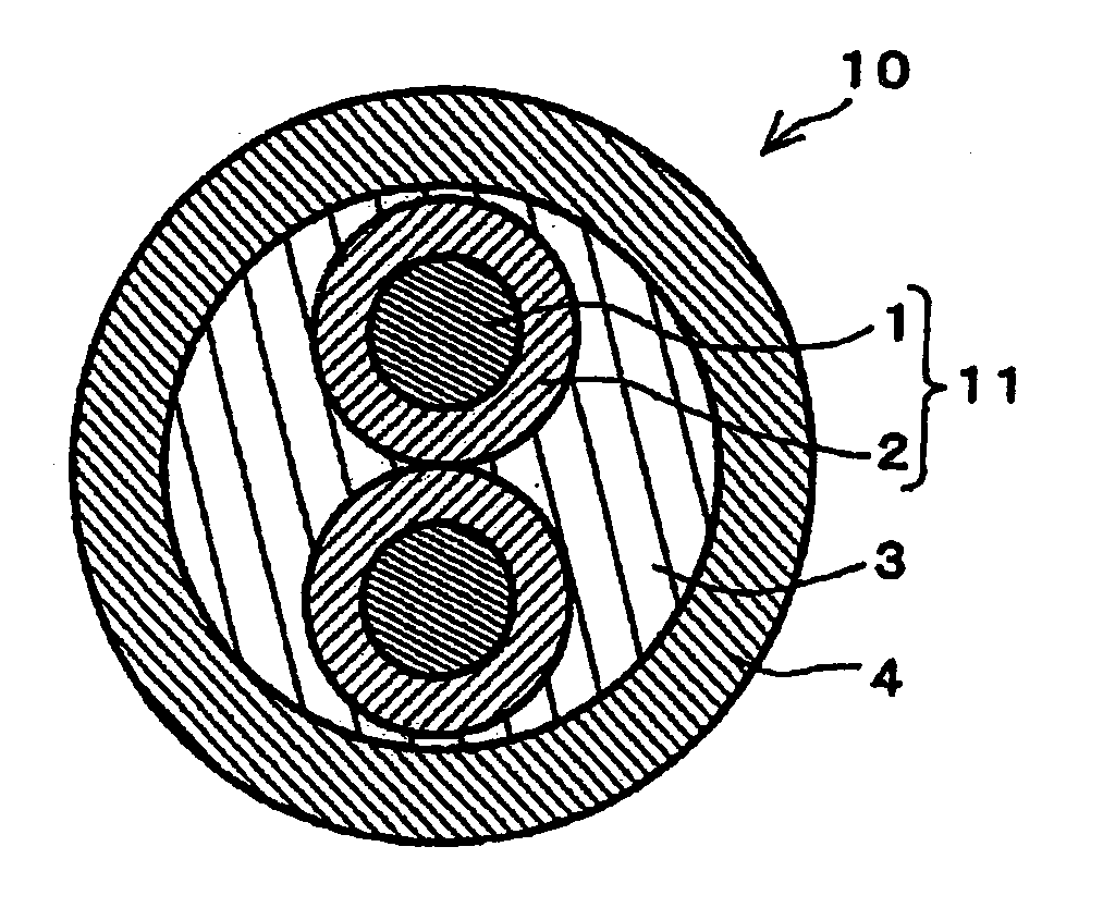
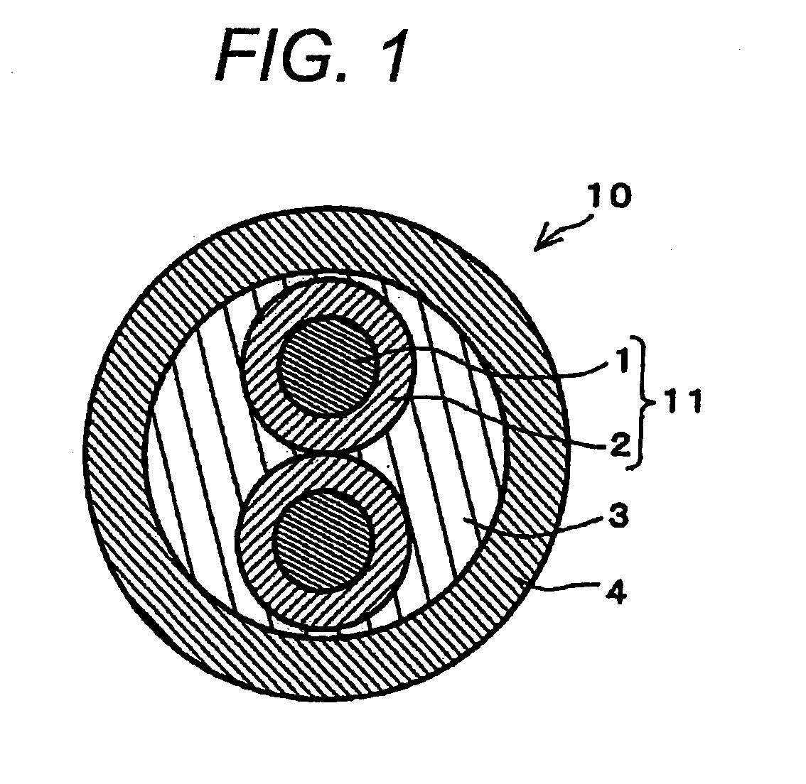
[0037]Cable shown in FIG. 1 may be fabricated in the following steps; the core may be formed with the twisted-pair of flame retardant electric wires and the intermediate material composed of polypropylene, next, the non-halogen resin compositions shown in Table 1 with its temperature maintained at 180° C. may be extruded on the core as a sheath (with approximately 1 mm thickness) by a 40mm extruding machine (with longitudinal diameter ratio L / D=24).


PUM

PropertyMeasurementUnit
Fractionaaaaaaaaaa
Percent by massaaaaaaaaaa

Abstract

An insulator 2 cladding the conductor 1 and / or a cable sheath 4 cladding the insulated electric wire 11 are formed by using a resin composition formed by mixing 100 to 250 parts by weight of silanized magnesium hydroxide together with 100 parts by weight of polymer composed of 50 to 80 parts by weight of ethylene-vinyl acetate copolymer, 10 to 30 parts by weight of polypropylene, and 10 to 20 parts by weight of magnesium hydroxide denatured with maleic acid obtained by denaturing copolymerized polymer with maleic anhydride, the copolymerized polymer being formed by copolymerizing ethylene and the co-monomer of alpha-olefin of carbon numbers 3 to 8.

Description

BACKGROUND OF THE INVENTION[0001]The present invention relates to non-halogen flame retardant resin composition and non-halogen flame retardant electric wires and cables, specifically to non-halogen flame retardant electric wires and cables which provide excellent flame retardant property and environmental compatibility.[0002]In recent years, non-halogen flame retardant electric wires and cables which are not composed of polyvinyl chloride or halogen flame retardant have become rapidly used widely as eco-friendly electric wires and cables. In the conventional non-halogen flame retardant electric wires and cables, it is general that the insulator for electric wires and the sheath for cables use resin compositions formed by mixing polyolefin together with non-halogen flame retardant such as magnesium hydroxide.[0003]These prior arts are disclosed, for example, in Japanese Publication Numbers P2003-160704A (2003) to K. KOBAYASHI et al of Riken Technos Corporation or P10-287777A (1998) ...

Claims


Application Information

Patent Timeline
IPC IPC(8): C08K3/34B32B1/08
CPCY10T428/1393C08K9/06
Inventor KIMURA, HITOSHI
Owner HITACHI METALS LTD
Learn More