Removal of a target gas from a mixture of gases by swing adsorption with use of a turboexpander

a technology of target gas and turboexpander, which is applied in the direction of separation process, dispersed particle separation, chemistry apparatus and processes, etc., can solve the problems of inability to make a complete separation and separate both components with a high recovery, and none of these to date present a viable solution to the problem of producing good light recovery and poor recovery of desired products

Active Publication Date: 2008-12-25
EXXON RES & ENG CO
View PDF62 Cites 53 Cited by
  • Summary
  • Abstract
  • Description
  • Claims
  • Application Information

AI Technical Summary

Benefits of technology

[0013]a) conducting said gas mixture to a turboexpander wherein the volume of said gas mixture is expanded, thereby lowering its pressure;

Problems solved by technology

Conventional PSA processes are typically able to recover only one of the key components (i.e., light or heavy) at high purity and are unable to make a complete separation and separate both components with a high recovery.
While there are various teachings in the art with respect to new adsorbent materials, new and improved parallel channel contactors, and improved rapid cycle PSA equipment, none of these to date present a viable solution to the problem of producing good recovery of the light component and purity when the feed gas is at very high-pressure.
This is a critical issue since natural gas is often produced at high pressures (500-7000 psi) and methane acts as a light component in the adsorption process.
One problem in extending PSA processes to high pressures, especially with those streams containing large amounts of CO2, is that at the end of the adsorption step there can be more moles of gas in the flow channels and mesopores then there are in the microporous sorbent.
This can lead to poor recovery of desired product and also to low purity product streams.
Another problem can be that at high pressures the isotherm of an adsorbent saturates.
This low slope decreases the effectiveness of the adsorbent, lowering recovery and decreasing the purity of the components recovered.
For example, purification of high CO2 content natural gas using PSA technologies is challenging because of: 1) the large volume of gas that must be processed; 2) the fact that all conventional adsorbents preferentially adsorb CO2; 3) the presence of impurities such as H2S, water, and higher hydrocarbons; 4) the very high pressures that makes minimization of voidage and dead spaces of the adsorbent critical; and 5) the fugacity of CO2 that significantly affects the physics of high-pressure adsorption and transport in microporous materials.

Method used


Image

  • Removal of a target gas from a mixture of gases by swing adsorption with use of a turboexpander
  • Removal of a target gas from a mixture of gases by swing adsorption with use of a turboexpander
  • Removal of a target gas from a mixture of gases by swing adsorption with use of a turboexpander

Examples


example 1

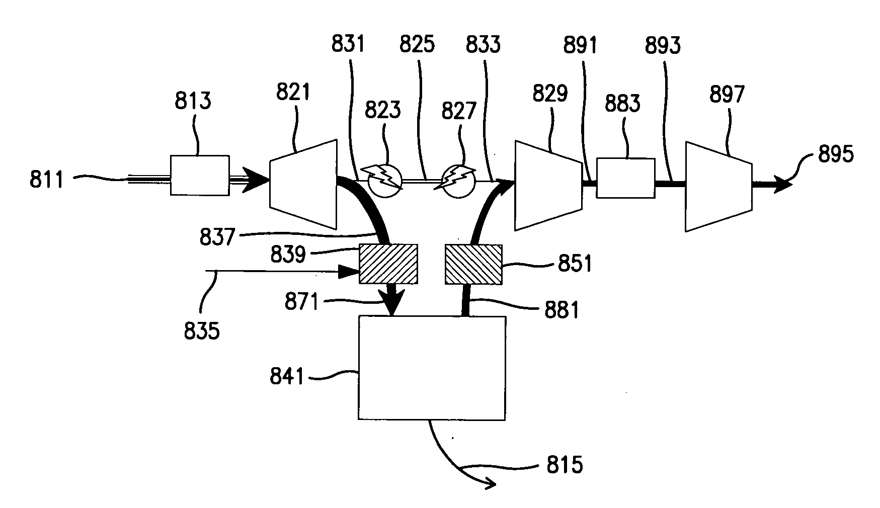
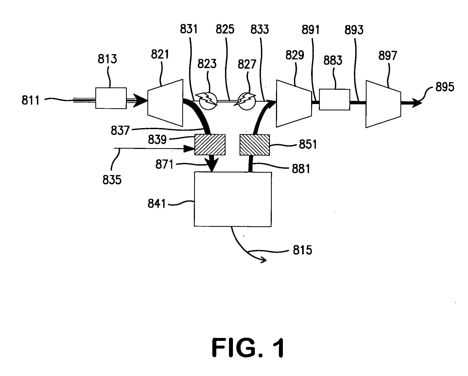
[0097]This example illustrates the use of a turboexpander to condition acid gas (i.e., natural gas containing H2S and CO2) so that PSA can operate in the window that optimizes methane recovery. FIG. 1 hereof shows a process scheme in which a turboexpander is used to set the pressure and temperature of an acid gas that is separated in a PSA. An acid gas stream 811 with a temperature of 100° C. and pressure of 1,500 psi is produced from a gas field and fed to the process. The CO2 content of the stream is about 66 mol % and the H2S concentration is 2 mol %. Water is present at its saturated vapor pressure and the concentration of the heavy hydrocarbons is about 2 mol %. The heavy hydrocarbons contain a small fraction of waxy species with carbon numbers as large as 36. For this stream 811, CO2 comprises the majority of the heavy component that will be removed by a kinetically controlled PSA process. If DDR zeolite is used as the adsorbent in the kinetically controlled PSA, the loading i...

example 2

[0102]With a laminated sheet parallel channel contactor described for FIG. 10 hereof, a PSA / RCPSA cycle with five steps is operated to produce a product stream containing about 20 vol % CO2 and about 80 vol % CH4. Overall methane recovery for the PSA / RCPSA cycle is computed to be about 95 vol %. FIG. 10 hereof is a schematic diagram of five different steps in a preferred PSA / RCPSA cycle suitable for use in this invention. In the first step 611a parallel channel contactor PSA / RCPSA cycle is pressurized with high pressure product gas 687. This pressurization raises the pressure in the parallel channel contactor and fills the contactor with the purified product containing about 20 vol % CO2 and about 80 vol % CH4. In a second step 621a high pressure, 51 atmosphere (atm) feed gas 671 is conducted through the parallel channel contactor. During this step 621 the DDR adsorbent layer adsorbs CO2 from the flowing feed gas 671. A purified product 625 flows out of the end of the contactor. The...

example 3

[0107]Using this parallel channel contactor, a PSA / RCPSA cycle with five different steps is operated to produce product stream containing about 2 vol % N2 and about 98 vol % CH4. Overall methane recovery for the PSA / RCPSA cycle is computed to be about 91 vol %. FIG. 11 hereof shows a schematic diagram of the five different steps in the PSA / RCPSA cycle. In the first step 711a parallel channel contactor PSA / RCPSA cycle is pressurized with high pressure product gas 787. This pressurization raises the pressure in the parallel channel contactor and fills the contactor with the purified product containing about 2 vol % N2 and about 98 vol % CH4. In a second step 721a high pressure 100 atm feed gas 771 is flowed through the contactor. During this step 721 the DDR adsorbent layer removes N2 from the flowing feed gas 771. A purified product 725 flows out of the end of the contactor. The feed gas 771 is flowed at a rate such that as the product 725 emerges from the contactor a concentration f...


PUM

PropertyMeasurementUnit
pore sizesaaaaaaaaaa
pressureaaaaaaaaaa
surface areasaaaaaaaaaa

Abstract

The separation of a target gas selected from a high pressure gas mixture containing said target gas as well as a product gas using a swing adsorption process unit. A turboexpander is used upstream of the swing adsorber to reduce the pressure of the high pressure gas mixture. A compressor is optionally used downstream of the swing adsorber to increase the pressure of the target gas-containing stream for injecting into a subterranean formation.

Description

CROSS REFERENCE TO RELATED APPLICATION[0001]This Non-Provisional Application claims the benefit of U.S. Provisional Application No. 60 / 930,827 filed May 18, 2007.FIELD OF THE INVENTION[0002]The present invention relates to the separation of a target gas from a high pressure gas mixture containing said target gas and a product gas using a swing adsorption process unit. A turboexpander is used upstream of the swing adsorber to reduce the pressure of the high pressure gas mixture. A compressor is optionally used downstream of the swing adsorber to increase the pressure of the resulting target gas-containing stream for injecting into a subterranean formation or to increase the pressure of the product gas.BACKGROUND OF THE INVENTION[0003]Gas separation is important in various industries and can typically be accomplished by flowing a mixture of gases over an adsorbent that preferentially adsorbs a more readily adsorbed component relative to a less readily adsorbed component of the mixture...

Claims


Application Information

Patent Timeline
Patent Type & Authority Applications(United States)
IPC IPC(8): B01D53/46B01D53/02B01D53/52B01D53/74B01D53/62B01D53/54
CPCB01D53/02B01D53/0423B01D53/0462B01D2253/108Y02C10/08B01D2253/342B01D2257/504B01D2259/4143Y02C10/04B01D2253/311Y02C20/40
Inventor DECKMAN, HARRY W.KELLEY, BRUCE T.THOMAS, EUGENE R.CHANCE, RONALD R.NORTHROP, PAUL S.CORCORAN, JR., EDWARD W.
Owner EXXON RES & ENG CO
Why Eureka
Try Eureka