

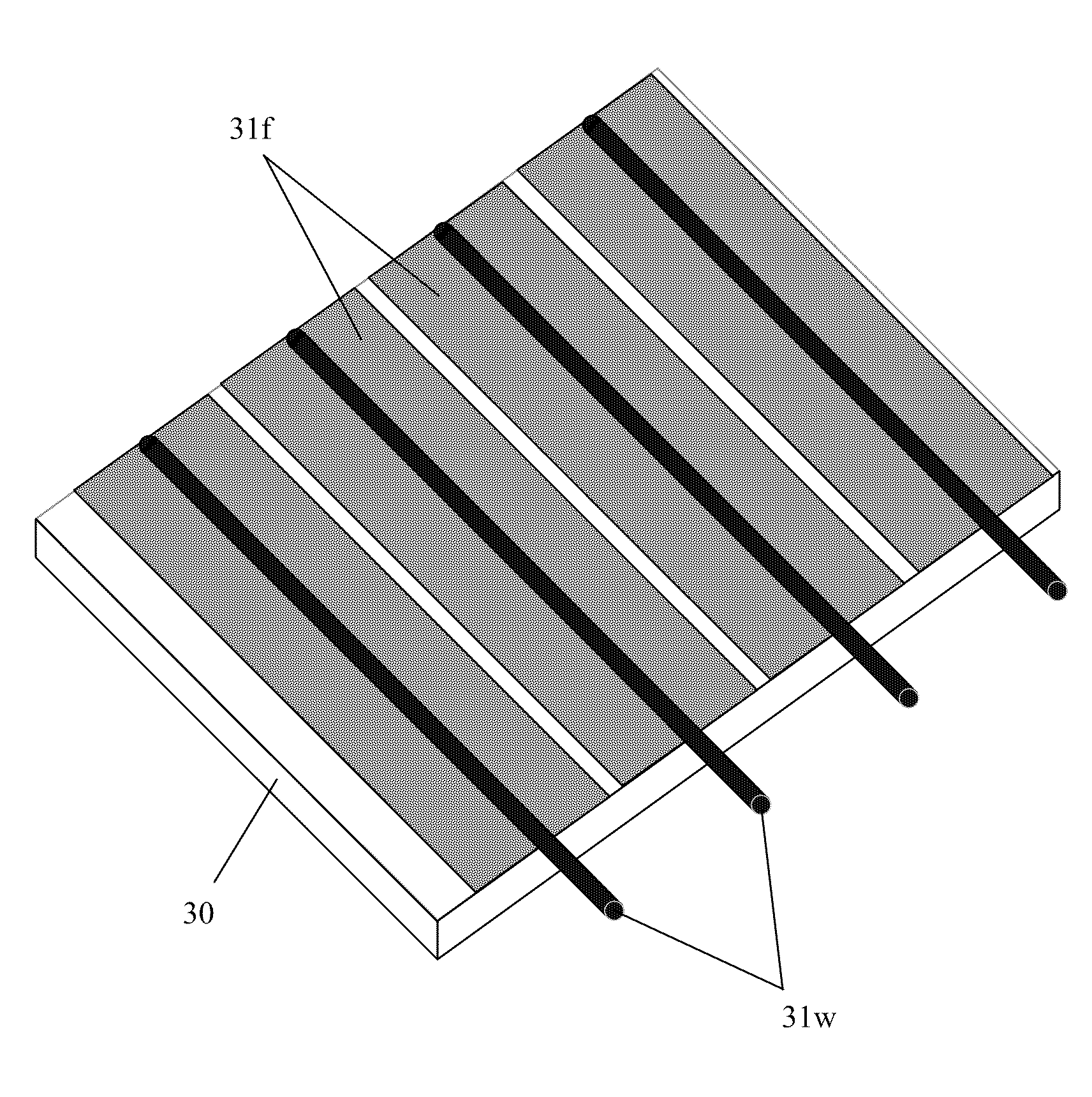
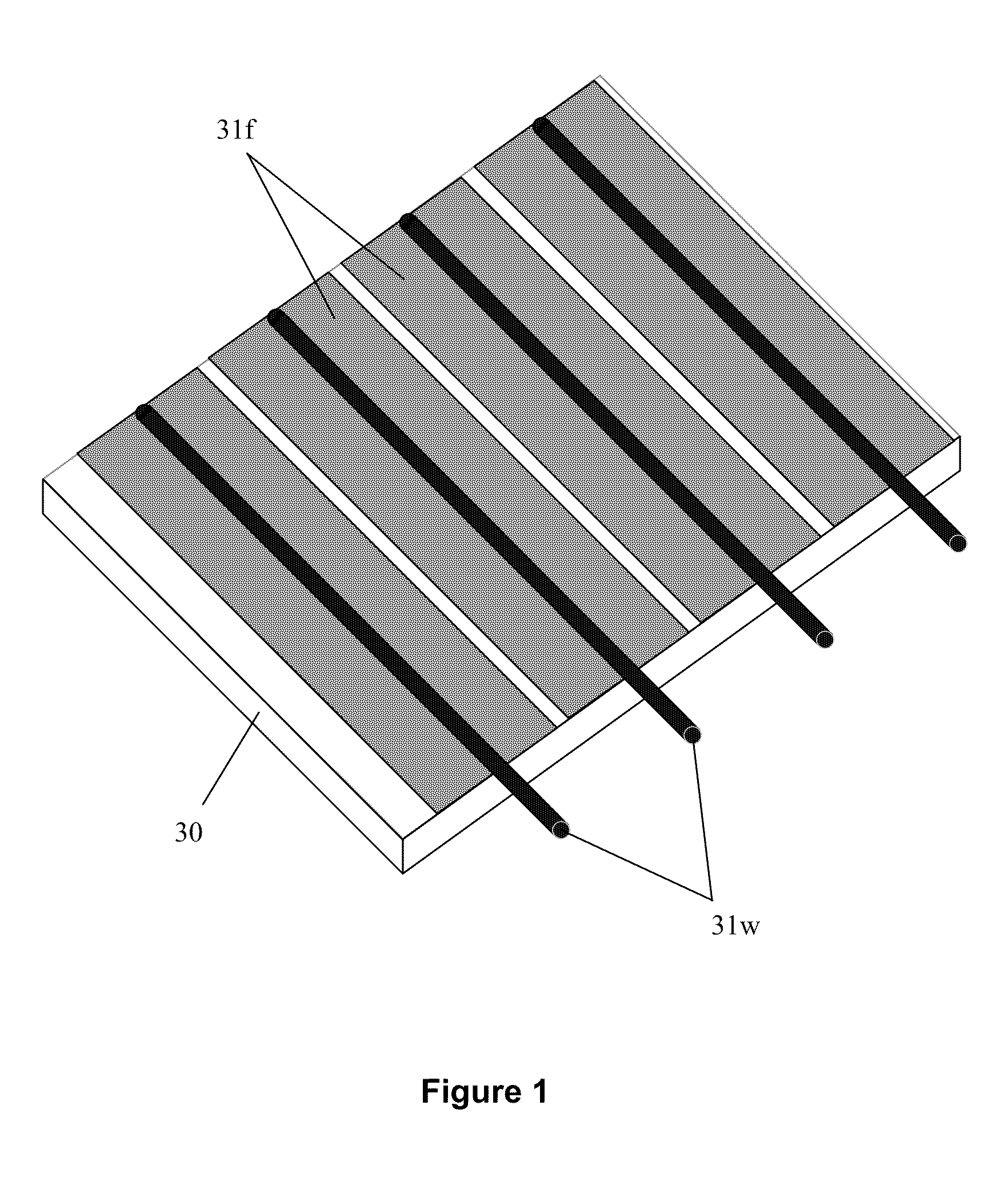
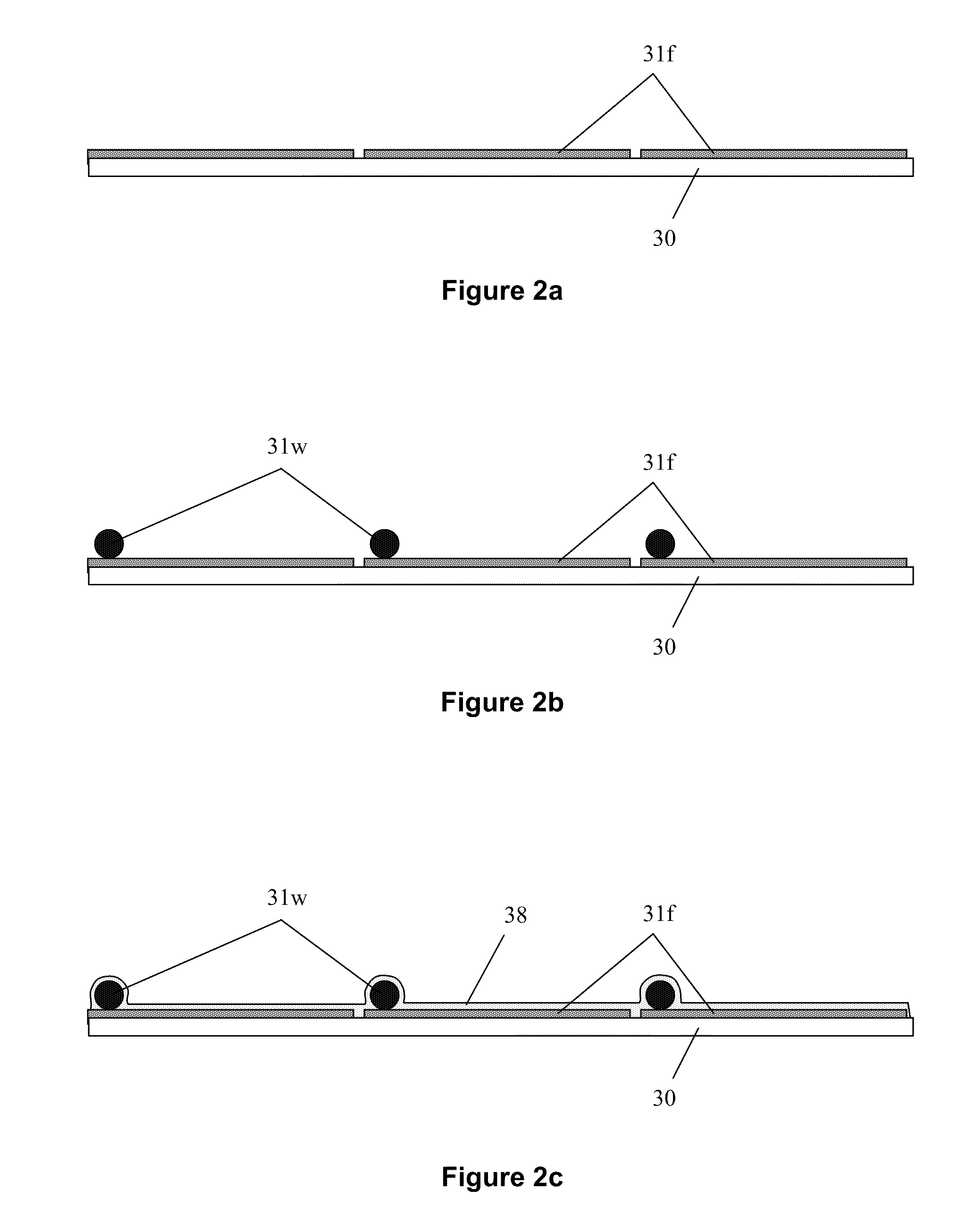
ELECTRODED SHEET (eSheet) PRODUCTS
a technology of electrode plates and electrodes, applied in the field of electrode plates, can solve the problems of limiting the size of the display, the size of the plasma-adressed back plane, and the creation of the top column electrode plates, and achieve the effect of good electrical connection and high conductivity
- Summary
- Abstract
- Description
- Claims
- Application Information
AI Technical Summary
Benefits of technology
Problems solved by technology
Method used
Image

Examples
example
[0204]This example uses an aluminum drum, 9″OD×6.5″L×¼″ walls (28.3″ circumference). A piece of polymer coated PET (MacTac TL5100 10 Mil Matte Polyester-7 mil thick Mylar® film with 3 mil thick polymeric adhesive) is cut 6″ wide by 25″ long. Double stick tape is used to attach both ends of the TL5100 film to the drum, polymer film facing outward. Once the TL5100 film is in place, 0.003″D Kovar wire is wrapped around the drum over the TL5100 film on a 0.100″ pitch. Next the drum is placed in an oven at 130° C. for ½ hour. Calculations show that the 9″D aluminum drum expands 0.0228″ in diameter going from 20° C. to 130° C., and the Kovar wire wrap diameter expands 0.0059″. This difference of 0.0169″ easily pushes the wires into the 0.003″ polymer coating. Once the drum is at 130° C. and the wire is sunk into the polymer film, the Kovar wire is stretched 0.0343″ for each turn on the drum resulting in a total stress on the wire electrode of 24,200 psi. Since the yield stress of Kovar is...
PUM
| Property | Measurement | Unit |
|---|---|---|
| Power | aaaaa | aaaaa |
| Electrical conductor | aaaaa | aaaaa |
Abstract
Description
Claims
Application Information