Optical Element and Method for Controlling Its Transfer Function

Inactive Publication Date: 2008-12-25
SWET OPTICS GMBH
View PDF1 Cites 5 Cited by
  • Summary
  • Abstract
  • Description
  • Claims
  • Application Information

AI Technical Summary

Problems solved by technology

This is extremely cost-intensive and is thus not suitable for mass production.
The disadvantage of this process is the need to use very high control voltages, which are determined by small electro-optical coefficients of the photorefractive materials used.
A further disadvantage is a small wave band of changeover to the amount of a maximum of 1 nm for LiNbO3 limited by the electrical discharge.
When this method is applied, however, there are limits to the number of switched spectral channels (which are determined by a maximum number of electrically multiplexed holograms) and the distance between adjoining channels.
This limit arises due to extremely high demands on modern data transfer system with regard to cross-talk.
The remaining gratings simultaneously cause additional noise.
This substantially increases the demands on stabilisation of the temperatures of this construction and limits the

Method used


Image

  • Optical Element and Method for Controlling Its Transfer Function
  • Optical Element and Method for Controlling Its Transfer Function
  • Optical Element and Method for Controlling Its Transfer Function

Examples


Embodiment Construction

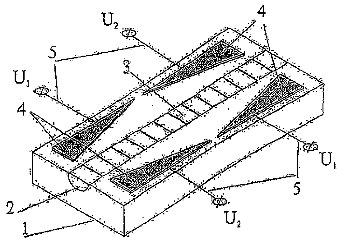
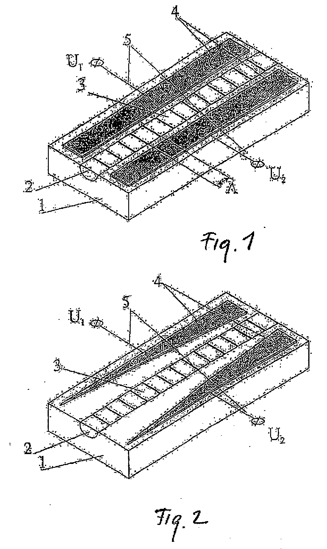
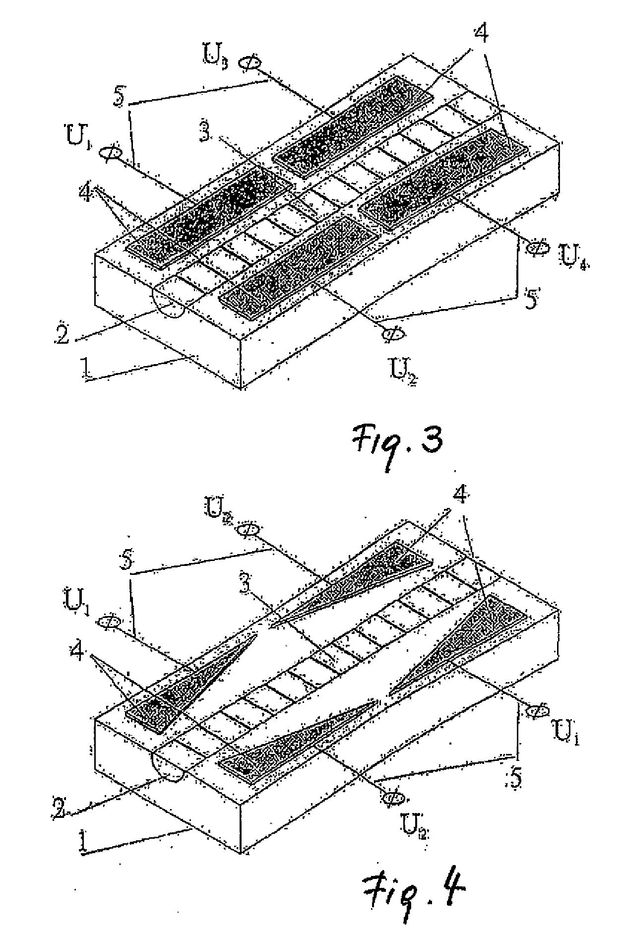
[0027]The object of the invention is, on the one hand, the production of optical elements in an integral optical design that have a multifunctional use (tuneable optical filters, selective optical attenuators and modulators, optical switches and optical equalisers), and which possess a high spectral selectivity, a broad wavelength band of tuneability, great dynamics, and a low tendency toward cross-talk. A further aim of this invention was to develop a process for control of the aforementioned elements that makes it possible to electrically control the profile of the transfer function, the location of the transfer function's maximum, the number of channels to be selected, and compensation of phase distortion, while using a relatively low control voltage, and with a high tuneability and switching speed. The task in hand is resolved by a large number of inventions that are related by one joint intention

[0028]Thus, the task in hand is resolved by virtue of the fact that the optical ele...


PUM


Abstract

Area: Optics
Optical element with Braggs phase grating that consists of electro-optical material or is embedded in an additional layer. The Braggs phase grating is designed as a series of periodically applied elevations and indentations of the waveguide's surface, coated with one layer of the compensating material and one layer of the electrically isolating material, along the propagation of light. The phase grating is equipped with a means of generating a spatially inhomogeneous, aperiodic, external electrical field.
Area of the Invention
The invention belongs to the physical area of optics and, in fact, to the optics methods and facilities for spectral filtering of optical radiation. This is based on electro-optical crystals and is to be used to produce narrow-band filters with a broad wave spectrum of changeover to wavelength, and for production of selective optical attenuators and modulators of light and optical equalisers.
Description of the Invention
The object of the invention is, on the one hand, the production of optical elements in an integral optical design that have a multifunctional use (tuneable optical filters, selective optical attenuators and modulators, optical switches and optical equalisers), and which possess a high spectral selectivity, a broad wavelength band of tuneability, great dynamics, and a low tendency toward cross-talk. A further aim of this invention was to develop a process for control of the aforementioned filters that makes it possible to electrically control the profile of the transfer function, the location of the transfer function's maximum, the number of channels to be selected, and compensation of phase distortion, while using a relatively low control voltage, and with a high tuneability and switching speed.
The task in hand is resolved by a large number of inventions that are related by one joint intention.

Description

FIELD OF THE INVENTION[0001]The invention belongs to the physical area of optics and, in fact, to the optics methods and facilities for spectral filtering of optical radiation. This is based on electro-optical crystals and is used to produce narrow-band filters with a broad wave spectrum of changeover to wavelength, and for production of selective optical attenuators and modulators of light and optical equalisers.BACKGROUND OF THE INVENTION[0002]The volume of information to be transmitted is currently growing disproportionately and is leading to the development of new technologies that make it possible to increase data transmission of the telecommunications networks One of the most future-oriented processes is condensing the signals in the channels of optical fibre-based data transmission networks (WDM—wavelength division multiplexing). In the near future, transmission of up to 80 spectral channels, with the generation of equidistant wavelengths from 1530 nm to 1600 nm, will make it...

Claims


Application Information

Patent Timeline
IPC IPC(8): G02F1/295
CPCG02B6/124G02B2006/12107G02F1/011G02F1/0311G02F1/0316G02F1/035G02F2201/307G02B6/34
Inventor PETROV, VICTOR
Owner SWET OPTICS GMBH
Why Eureka
Try Eureka