
Treatment of implantable medical devices resistant to calcification

Inactive Publication Date: 2008-12-25
LAB PEROUSE
View PDF7 Cites 14 Cited by
  • Summary
  • Abstract
  • Description
  • Claims
  • Application Information

AI Technical Summary

Benefits of technology

[0018]The inventors have now proved that the succession of steps (A), (B) and (C) allows an increased level of biocompatibility to be conferred to a protein-based implant whilst also limiting the occurrence of calcification of said implant.
[0019]In particular, inventors' studies have made it possible to establish that the combination of steps (B) and (C) makes it possible to strongly reduce the occurrences of calcification which are observed with implants currently known, which correspond to implants treated solely according to step (A) of the present invention.
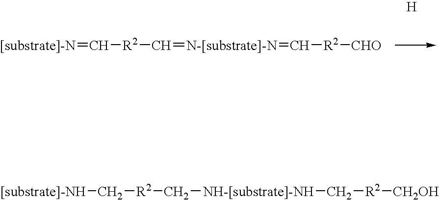
[0020]The limitation of the occurrence of calcification seems, in part, to be explained by the fact that the succession of steps (B) and (C) allows the number of free aldehyde functions introduced in step (A) to be reduced to alcohol functions (in step (B)), said alcohol functions being protected in the form of siloxane functions (in step (C)). Said siloxane functions have the advantage of being stable functions which are biocompatible and not very conducive to the accumulation of calcium salts.
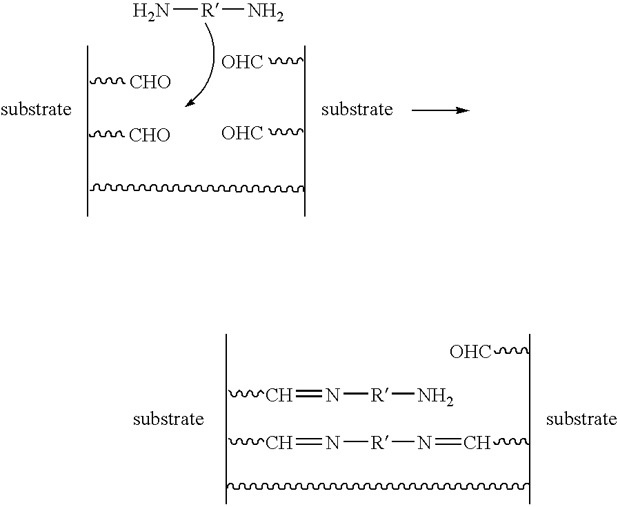
[0021]Also, it has further been proven that the reduction step (B) leads, in addition to the effect mentioned above, to a reduction of other functions introduced in step (A). More precisely, step (B) leads to the reduction of imine functions resulting from the coupling of free amines of the substrate of the implant to the difunctional aldehydes of step (A). This reaction of the imine functions is particularly advantageous since it has been proven that said imine functions also aid calcification. Step (B) thus makes it possible to delete imine groups capable of inducing calcification by converting them into substituted amine functions which have the advantage of being stable.
[0022]Thus, the method of the invention makes it possible to limit the occurrence of calcification by inhibiting the presence of two sources responsible for calcification of the implant. Consequently, the implant prepared according to the method of the invention has the advantage of having a low rate of calcification, which makes it possible, in certain cases, to avoid replacing the implant by means of a surgical procedure, or at least to stagger the timing of surgical procedures necessary to replace the implant.

Problems solved by technology

However, protein-based implants treated with glutaraldehyde-type compounds generally lead to rather rapid calcification of the implant when said implant is placed inside a living body.
The calcification results in a hardening of the implant due to the accumulation of calcium salts at the implant.
This impairs the properties of the implant, particularly in the use of cardiac or vascular prostheses, which requires periodic replacement of the implant by surgical means.
These types of treatment fundamentally aim, in fact, to eliminate the presence of toxic by-products and do not sufficiently limit calcification.

Method used


Image

  • Treatment of implantable medical devices resistant to calcification
  • Treatment of implantable medical devices resistant to calcification

Examples


example 1

Treatment of Substrate According to Steps (A) (B) and (C) of the Method of the Invention

[0096]Treatment with Glutaraldehyde Solution (S1)

[0097]The substrate was treated with solution (S1) for at least one month at ambient temperature (approximately 25° C.).

[0098]At the end of said treatment, the treated substrate was cut into squares measuring 8 mm, approximately 7 mm, on each side.

[0099]The samples resulting from the substrate thus treated were rinsed three times with ultra pure water.

[0100]Treatment with Sodium Cyanoborohydride Solution (S3)

[0101]Said rinsed samples were transferred to a 150 ml bottle with a rectangular cross-section containing approximately 100 ml of solution (S3). The reaction medium was then stirred at approximately 50 rpm−1 at ambient temperature (approximately 25° C.) for approximately 24 hours.

[0102]The samples thus treated were rinsed three times with ultra pure water.

[0103]Treatment with Chloromethylsilane Solution (S4)

[0104]The samples thus rinsed were tr...

example 2

Treatment of the Substrate According to Steps (A), (A1), (B) and (C) of the Method of the Invention

[0106]Treatment with Glutaraldehyde Solution (S1)

[0107]The substrate was treated with solution (S1) for at least one month at ambient temperature (approximately 25° C.).

[0108]At the end of said treatment, the treated substrate was cut into squares measuring approximately 7 mm on each side.

[0109]The samples resulting from the substrate thus treated were rinsed three times with ultra pure water.

[0110]Treatment with poly(propylene glycol)bis(2-aminopropyl ether) (Jeffamines) Solution (S2)

[0111]The samples thus rinsed were transferred to a 150 ml bottle with a rectangular cross-section containing 100 ml of solution (S2). The bottle was stirred at approximately 50 rpm−1 for approximately 1 hour at ambient temperature (approximately 25° C.).

[0112]Approximately 5.76 g of morpholinoethanesulfonic acid (MES) were added to the reaction medium. The reaction medium was stirred at approximately 50 ...

example 3

Treatment of the Substrate According to Steps (A) (A1), (B) and (C) of the Method of the Invention

[0121]The same procedure was repeated except that in the last step (C) the trimethylsilylimidazole solution (S5) was used instead of the chloromethylsilane solution (S4).


PUM


Abstract

Treatment of implantable medical devices resistant to calcification The invention relates to a method for treating an implant comprising a protein-based substrate, including the following steps in which:(A)—the protein-based substrate is treated with a compound containing at least one aldehyde group, then(B)—the substrate is treated with a compound comprising a borohydride, then(C)—the substrate resulting from step (B) is treated with a derivative containing a silane group.The invention also relates to the treated protein-based implant obtained at the end of this method.

Description

TECHNICAL FIELD[0001]The present invention relates to implantable medical devices (referred to hereinafter by the generic term “medical implant”). More precisely, the invention relates to protein-based medical implants, in particular collagen-based medical implants, rendered biocompatible and resistant to calcification, and more specifically to a method for preparing implants of this type.BACKGROUND TO THE INVENTION[0002]Different types of medical implant exist, among which protein-based implants are included which are of particular benefit. These implants are particularly more advantageous than non-biological material-based implants in that they make it possible to avoid, inter alia, thromboses when they are inserted into a living organism, in particular into humans. However, in order to obtain such a biocompatibility, protein-based implants must be pre-treated.[0003]The proteins present in the protein-based implants are, in fact, generally fibrous proteins (typically collagens) wh...

Claims


Application Information

Patent Timeline
IPC IPC(8): C07K1/107C07K14/75C07K14/78C07K14/745
CPCA61L27/22A61L27/3604A61L27/3625Y02P20/582A61L27/3645A61L27/3687A61L27/3641
Inventor SHEN, MING
Owner LAB PEROUSE
Learn More