Cervical dilator catheter

a catheter and cervix technology, applied in the field of cervical dilator catheters, can solve the problems of limiting the patient's mobility, uterine hyperstimulation and fetal distress, and the method is often a prolonged process, so as to shorten the length of labor, facilitate the insertion through the cervix, and facilitate the effect of catheter insertion

Inactive Publication Date: 2008-12-25
SHELLEY MARION STEVENS
View PDF3 Cites 22 Cited by
  • Summary
  • Abstract
  • Description
  • Claims
  • Application Information

AI Technical Summary

Benefits of technology

[0005]The present invention provides an improved single balloon catheter that is intended to dilate the cervix, initiate uterine contractions, and therefore shorten labor. It is approximately 42 cm in length and 2.5 mm to 4 mm in diameter. It has a balloon on the distal end, just below the drainage outlet, that when inflated it has a disc shape with a diameter of 6 cm to 8 cm and a height of 3 cm to 4 cm. The total volume should be about 100 ml to 120 ml.
[0008]Prior to inflation of the balloon the distal end of the catheter is placed through the undilated or partially dilated (0-1 cm) cervix with the stylet in place to guide the catheter through the cervix. Once the distal end with the balloon is through the cervix and in the uterine region, a syringe is utilized to inject 100 to 120 ml of sterile water or normal saline into the balloon. As the balloon is inflated it lifts the amniotic membrane off of the cervix, therefore sweeping the membrane which causes the release of prostaglandins which initiate cervical ripening and uterine contractions. The stylet is then removed, and the catheter is pulled taut and secured with adhesive tape to the patients' thigh. This causes a downward pressure on the cervix that imitates the fetal head. The patient can then walk which would provide continual stimulation of the cervix causing uterine contractions or oxytocin can be administered intravenously with the catheter being tugged gently at regular intervals when patient ambulation is not possible. When the catheter is expelled, the patient will be 6 cm to 8 cm dilated. This invention could shorten the length of labor significantly, therefore decreasing the number of ceasarean deliveries due to failure to dilate.

Problems solved by technology

This method is often a prolonged process, especially if the cervix is unfavorable for dilation.
It also requires the patient to be on continuous fetal monitoring which limits the patient's mobility.
It involves patient discomfort and can cause uterine hyperstimulation and fetal distress.
Another method is the administration of cytotec to the cervix, however the results can be unpredictable.
It can lead to uterine hyperstimulation and uterine rupture, which places the baby and the mother at risk for death.
Another drawback is that it is difficult to remove from the cervix if hyperstimulation does occur.
Other methods used to ripen the cervix include prostaglandin gels applied to the cervix which also can take many hours to work as well as cause various unwanted side effects such as nausea, vomiting, diarrhea, dysrhythmias and uterine hypertonus.
Laminara has also been used to ripen the cervix, but it is uncomfortable and unreliable, and it can also take many hours for it to ripen the cervix so that the induction may be started.
However these catheters can be uncomfortable to have placed, due to most providers using a speculum to visualize the cervix and then they thread the catheter in with a pair or ring forceps.
Another disadvantage is that no matter how much more water is placed in the balloon, it will only have a diameter of 4-5 cms.
Although this can be risky if the catheter tip becomes clogged because the saline can build up causing an abruption.
This could significantly lower the number of cesarean deliveries done because of the cervix's failure to dilate.

Method used


Image

  • Cervical dilator catheter
  • Cervical dilator catheter
  • Cervical dilator catheter

Examples


Embodiment Construction

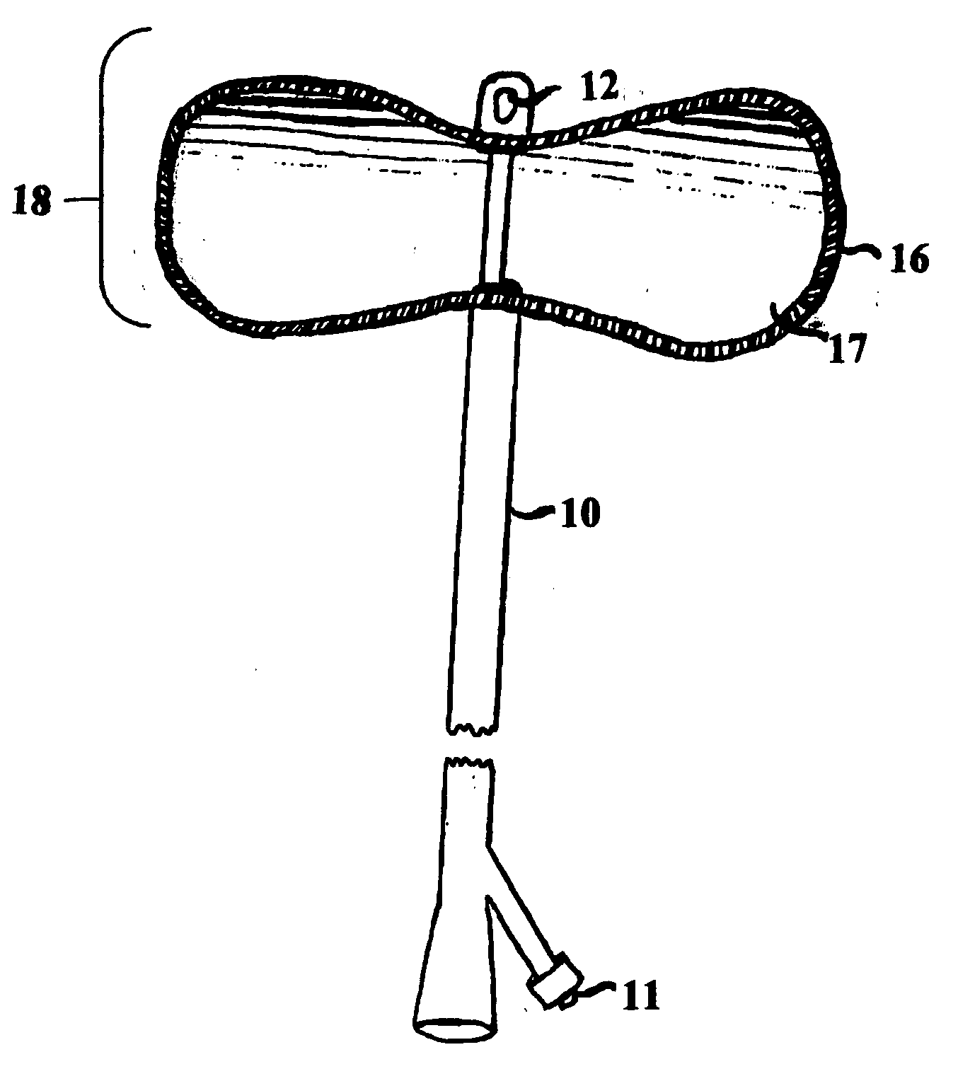
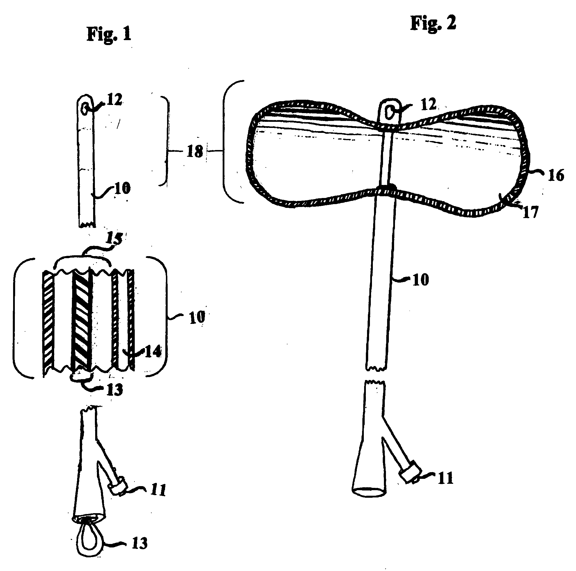
[0013]The catheter as illustrated in FIG. 1 comprises a slender, flexible tube 10 that has an outlet port 12 on the side of the distal tip, this allows for drainage of amniotic fluid through the main lumen 15 of the catheter. There is a fixed inflatable balloon 16 on the distal end as shown in FIG. 1 and FIG. 2. This balloon 16 is inflated with sterile water 17 or normal saline 17 as shown in FIG. 2. The liquid is introduced into the balloon 16 through an injection port 11 and through the inflation tube 14. The balloon 16 is disc-shaped, measuring approximately 3-4 cm in height with a diameter of 6-8 cm when inflated as shown in FIG. 2. The catheter 10 also accommodates a flexible, bendable, removable plastic stylet 13 in the main lumen 15 of the catheter, as shown in FIG. 1.

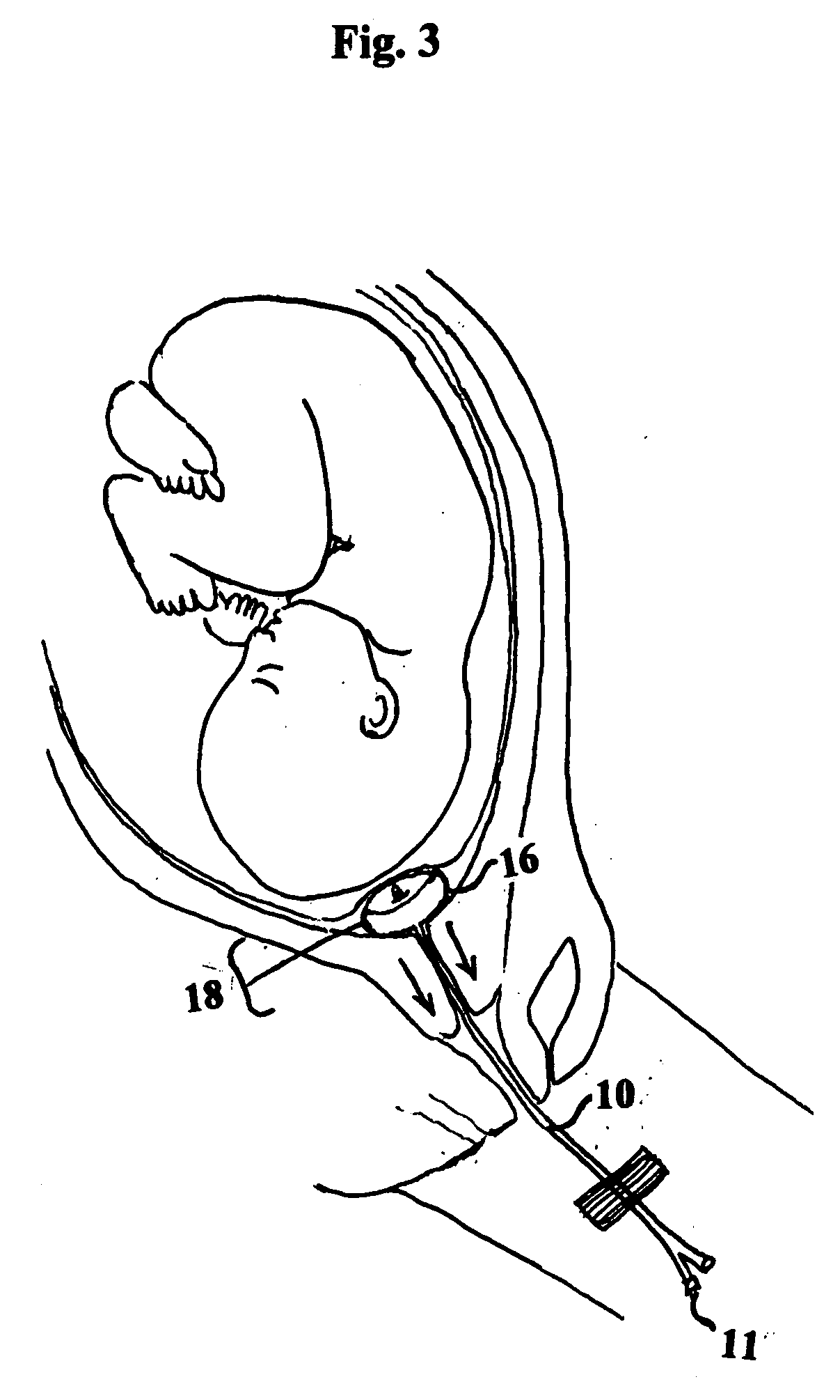
[0014]FIG. 3 illustrates placement of the catheter of the catheter 10 in the cervical region of the uterus for use as a cervical dilator. With the balloon 16 deflated, and with the stylet 13 in place the provide...


PUM


Abstract

This invention is an improved balloon catheter for cervical dilation. This catheter has a balloon that is passed through the cervix of a pregnant woman, and the balloon is then inflated with 100-120 ml of sterile water or normal saline. The improved disc shape of the inflated balloon is 8 cm in diameter and 3-4 cm in height. The balloon will sweep the amniotic membrane away from the cervix, causing the release of prostaglandins which helps ripen the cervix and initiates uterine contractions. The improved shape of the balloon causes the cervix to be 6-8 cm dilated once it is expelled. This catheter also contains a flexible guidewire that allows for easier insertion for the provider, and makes insertion less painful for the patient because it can be placed without a speculum and ring forcep being used. This catheter could actually be placed on an outpatient basis or in the doctor's office, with the patient instructed to go to the hospital or birthing unit when the catheter falls out. This catheter is smaller in diameter than the 16 French Foley catheter, so therefore it can be placed when the patient is <1 cm dilated. This catheter when placed properly and secured to the patient's thigh with tension applied can shorten labor by 4-10 hours.

Description

BACKGROUND OF THE INVENTION[0001]Induction of labor has always been dependant on the favorability of the cervix to dilate. In order to induce labor many different medications and devices are currently utilized to bring about cervical dilation. The most widely used method is intravenous administration of oxytocin. This method is often a prolonged process, especially if the cervix is unfavorable for dilation. It also requires the patient to be on continuous fetal monitoring which limits the patient's mobility. It involves patient discomfort and can cause uterine hyperstimulation and fetal distress. Another method is the administration of cytotec to the cervix, however the results can be unpredictable. It can lead to uterine hyperstimulation and uterine rupture, which places the baby and the mother at risk for death. Another drawback is that it is difficult to remove from the cervix if hyperstimulation does occur.[0002]Other methods used to ripen the cervix include prostaglandin gels a...

Claims


Application Information

Patent Timeline
Patent Type & Authority Applications(United States)
IPC IPC(8): A61M29/02
CPCA61B17/0218A61B17/42A61B2017/00539A61B2017/00557A61B2017/22062A61B2017/4225A61M29/02A61M2210/145
Inventor SHELLEY, MARION STEVENS
Owner SHELLEY MARION STEVENS
Why Eureka
Try Eureka