
Zeolite membrane structures and methods of making zeolite membrane structures

a technology of zeolite and membrane structure, applied in the field of zeolite membrane structure, can solve the problems of difficulty in obtaining such a zeolite membrane, high cost, and limited quality of zeolite membrane, and achieve the effect of improving energy and capital efficiency

Inactive Publication Date: 2009-01-01
CORNING INC
View PDF20 Cites 70 Cited by
  • Summary
  • Abstract
  • Description
  • Claims
  • Application Information

AI Technical Summary

Benefits of technology

[0022]Inorganic membrane structures of the present invention can be used for separation in processing industries with enhanced energy and capital efficiency, for example, CO2 capture from flue gas streams

Problems solved by technology

However, sequentially immersing a porous support into various reactant solutions causes the distribution of reactions in the pores of the porous support to be irregular, resulting in zeolite membranes having significantly limited quality.
Obtaining such a zeolite membrane is challenging because of defects typically found in the zeolite membrane.
Obtaining functional zeolite membranes from high alkaline syntheses routes is difficult since the heterogeneous crystals in the zeolite membrane require an enormous membrane thickness to seal pinholes and void structures which lowers the membrane selectivity.
The presence of such pinholes and voids can cause optical scattering in the synthesized high alkaline membrane.
One difficulty arises in the complex method of forming this zeolite membrane.
The disk or tubular zeolite membrane structures possess low surface area packing density and impose large manufacturing and engineering costs on unit membrane separation area basis, which hinders widespread application of zeolite membranes.
Disadvantages of conventional membrane synthesis process include, for example, a long synthesis time, excessively large zeolite crystals, no preference of zeolite crystal growth on an internal surface of a channel or an internal surface of a tube, a limited number of nucleation sites on the substrate and therefore low volume density of zeolite crystals, difficulty in forming a zeolite membrane minimizing pinholes and excessively thick zeolite membranes.

Method used


Image

  • Zeolite membrane structures and methods of making zeolite membrane structures
  • Zeolite membrane structures and methods of making zeolite membrane structures
  • Zeolite membrane structures and methods of making zeolite membrane structures

Examples


example 1

Preparation of Silicalite-1 and ZSM-5 Seed Layer Particles

[0080]Silicalite and ZSM-5 are MFI type zeolites. In this example, silicalite-1 and ZSM-5 seed particles are grown utilizing a reflux method.

[0081]In the silicalite-1 seed synthesis, a synthesis solution was prepared with tetraethylorthosilicate (TEOS, 98%, Alfa Aesar), tetrapropylammonium (TPAOH, 40%, Alfa Aesar), pure H2O and NaOH. The molar ratio of TEOS / TPAOH / H2O / NaOH was 1 / 0.15 / 18.8 / 0.008. The synthesis solution was prepared at room temperature. In this preparation, H2O and NaOH were first mixed together and then, TPAOH was added while stirring at room temperature. TEOS was then added drop-wise while stirring. The synthesis solution was continuously stirred for 24 hours. The final synthesis solution was clear in color.

[0082]The reflux seed synthesis was conducted at 85° C. for 72 hours. The final synthesis solution was filtered with No. 40 filter paper to remove large particles having diameters greater than 1 micron. The...

example 2

Coating of Zeolite Seeding Crystals on Alpha-Alumina Inorganic Porous Supports

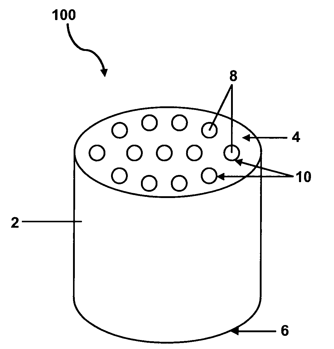
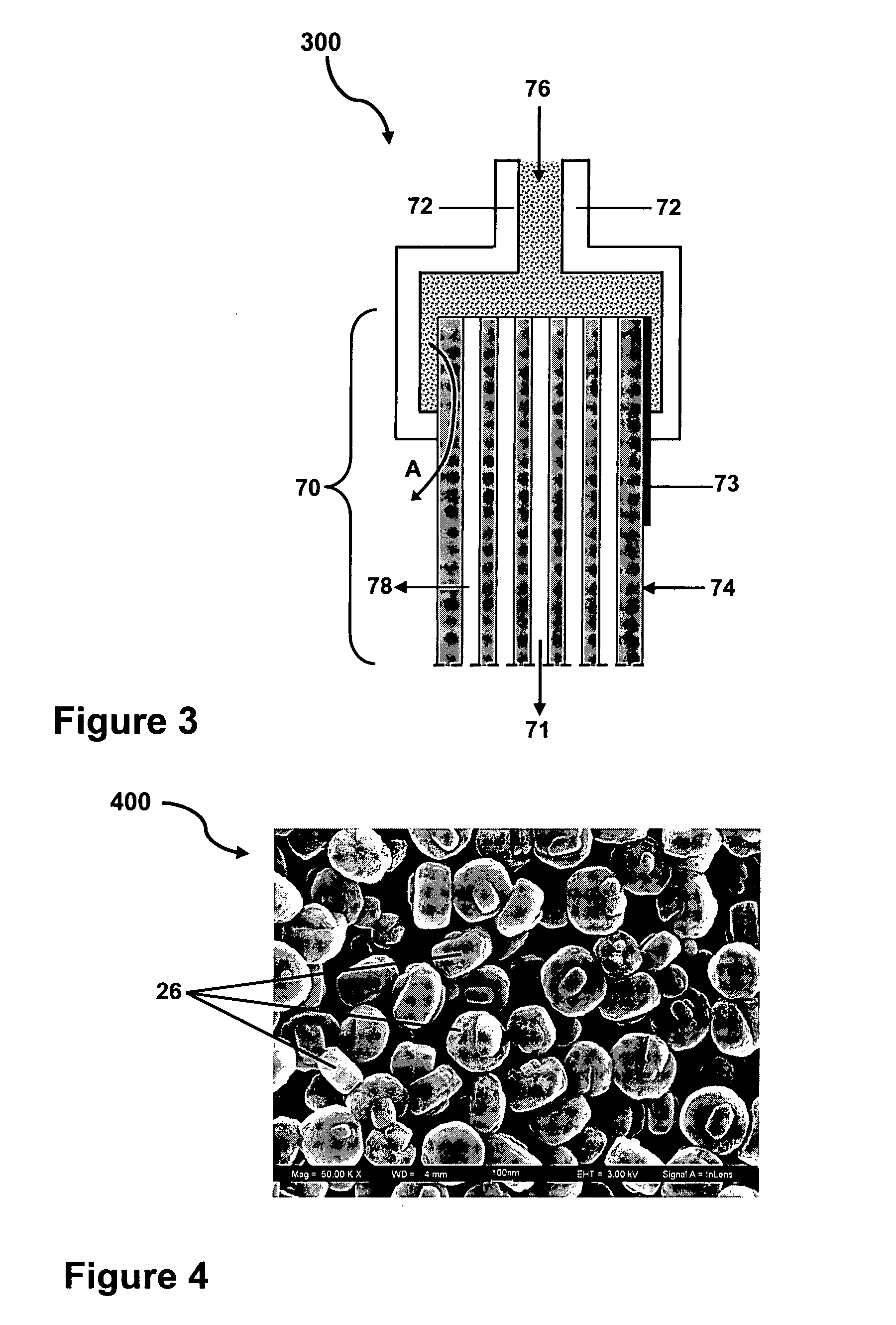
[0087]In this example, the silicalite-1 seeds similar to those shown in FIG. 4 were flow-coated onto two pure α-Al2O3 honeycomb monolith inorganic porous supports with two different pore sizes on the top intermediate layer; one having a median pore size of about 200 nm, the other having a median pore size of about 800 nm. The honeycomb monolith inorganic porous supports had an outer diameter of about 9.7 mm with 19, 0.8 mm rounded inner channels uniformly distributed over the cross-sectional area of the honeycomb monolith inorganic porous supports. The honeycomb monolith inorganic porous supports were made of alpha-alumina with a median pore size of about 10 μm and a median porosity of about 45%. The inner channel surfaces of the honeycomb monolith inorganic porous supports were modified with intermediate layers of alpha-alumina material.

[0088]The zeolite seed layer coating slips were the same for both ho...

example 3

Preparation of Intergrown, Dense Silicalite-1 Layer with a Microwave Assisted Hydrothermal Reaction Method

[0091]The silicalite-1 seed coated support samples were processed by a secondary growth with a microwave assisted hydrothermal reaction method for intergrowth of the zeolite seed layer to form a dense silicalite-1 membrane. The synthesis solution for the secondary growth was prepared with the same material as used for the seed growth described in Example 1, but with a molar ratio of TEOS / TPAOH / H2O=1 / 0.12 / 5.8. The microwave assisted secondary growths were carried out using a Milestone 1600 microwave reactor with a 100 ml Teflon® autoclave.

[0092]2½ inch long honeycomb monolith inorganic porous supports with inner channel surfaces modified with intermediate layers of alpha-alumina material, coated with the silicalite-1 seed layer, dried and fired were vertically put into the Teflon® autoclave and immersed in the synthesis solution. The reaction condition was set at 400 Watts microw...


PUM

PropertyMeasurementUnit
Pore sizeaaaaaaaaaa
Pore sizeaaaaaaaaaa
Pore sizeaaaaaaaaaa

Abstract

Inorganic membrane structures of high stability, high permeability, and large surface area. Zeolite membranes can be disposed onto an intermediate pore size modification layer which reduces the pore size of the inorganic porous support. The intermediate pore size modification layer minimizes the defects in the zeolite membrane and provides a more continuous and uniform zeolite membrane. The inorganic membrane structure can be in the form of a honeycomb monolith. The applications for the zeolite membranes include, for example, membrane ultra-filtration of gas or liquid fluids, biological assays and cell culture surfaces.

Description

BACKGROUND[0001]1. Field of the Invention[0002]The present invention relates generally to zeolite membrane structures and more particularly to zeolite membrane structures useful for molecular-level separation and methods of making the same.[0003]2. Technical Background[0004]In the field of membrane separations, membrane materials deposited on porous supports are widely used for micro-filtration or ultra-filtration of liquid media and gas separation. The porous support functions to provide mechanical strength for the membrane materials.[0005]Inorganic porous supports can be deposited with inorganic coatings to form a membrane structure for use in filtration and separation applications in the environmental, biological, food and drink, semiconductor, chemical, petrochemical, gas and energy industries. These industries often require purified gas / vapor or purified liquid whose source is a mixed feed stream composed of different gas and / or liquid / particulate combinations. Specific example...

Claims


Application Information

Patent Timeline
IPC IPC(8): B01D53/047B01J20/02B01J20/28
CPCB01D53/228B01D63/066B01D67/0051B01D69/12B01D71/028B01D2256/22B01D2325/02B01J29/40B01J35/065B01J37/0244B01J2229/64Y02C10/08B01D69/105B01J29/035Y02C20/40B01J35/59B01D71/0281B01D2325/02831
Inventor FEKETY, CURTIS ROBERTKINNEY, LYLE DAVIDLIU, WEISONG, ZHEN
Owner CORNING INC
Learn More