Method of Mixing and Extruding Viscous Materials and Gearbox for Dispensing the Same

a technology of viscous materials and gearboxes, which is applied in the direction of dynamo-electric machines, opening closed containers, and containers, etc., can solve the problems of difficult to achieve high torque at low speed, low torque at high speed, and difficult to achieve high speed at low speed, and achieve high torque at high speed. , the effect of complex drive and changing gears

Inactive Publication Date: 2009-01-01
3M ESPE
View PDF13 Cites 12 Cited by
  • Summary
  • Abstract
  • Description
  • Claims
  • Application Information

AI Technical Summary

Benefits of technology

[0068]It may be provided that the gearbox is adapted that when the first output drive shaft is driven by the first motor and the second motor at the same time, the speed of the first output drive shaft is dominated by the first motor and high speed is applied to said first output drive shaft. This may occur for example if the plungers are positioned with low resistance so that the load on the motors is low.
[0069]It may be provided that the gearbox is adapted that when the first output drive shaft is driven by the first motor and the second motor at the same time, the speed of the first output drive shaft is dominated by the second motor and high torque is applied to said first output drive shaft. This may occur for example if the plungers are pressed against the components in the cartridge so that the load on the motors is high.

Problems solved by technology

It is difficult to achieve both high torque at low speed, and also low torque at high speed, without changing gears.
It is also difficult to achieve highly different speeds, e.g., differing by a magnitude of 100, using a linear drive of any kind without changing gears or using clutch-like devices.
The changing of gears typically requires a complicated drive.
Furthermore, it is very difficult or sometimes even impossible to change gears under load.
Devices that can perform these functions can as a result be complicated and expensive.

Method used


Image

  • Method of Mixing and Extruding Viscous Materials and Gearbox for Dispensing the Same
  • Method of Mixing and Extruding Viscous Materials and Gearbox for Dispensing the Same
  • Method of Mixing and Extruding Viscous Materials and Gearbox for Dispensing the Same

Examples


first embodiment

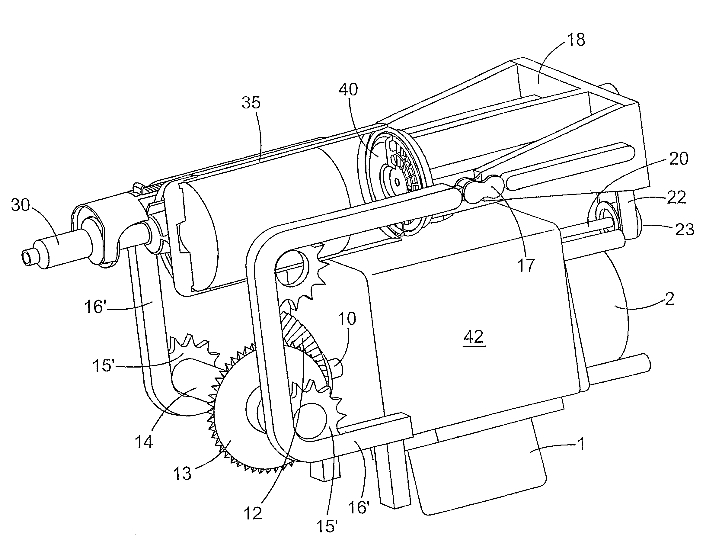
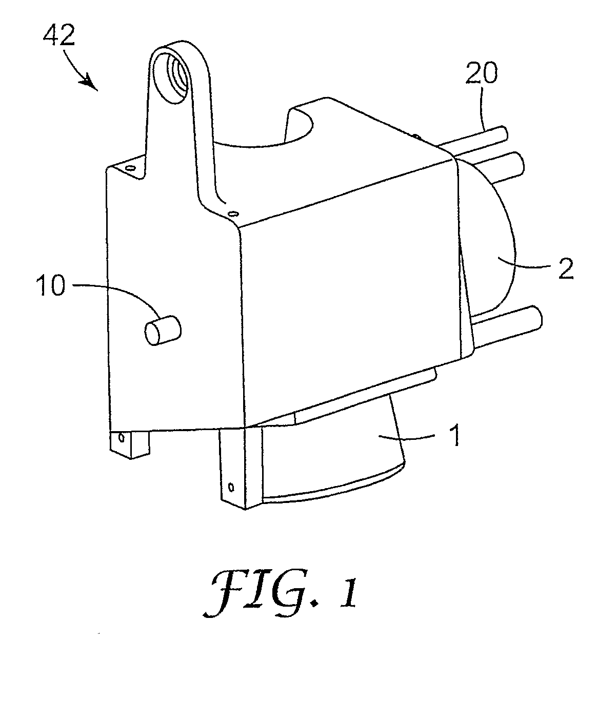
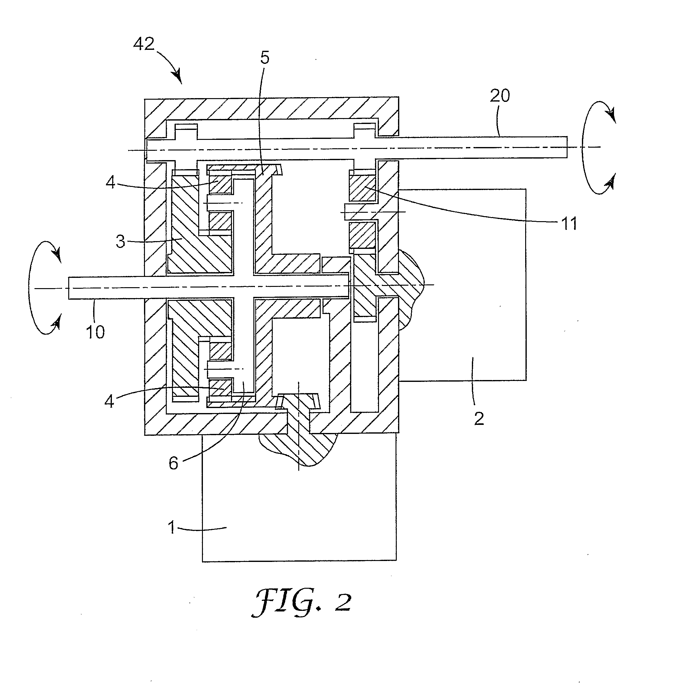
[0100]FIGS. 2 and 4 show a drive unit where the superimposing gear drive is a planetary gear drive. In this case, the above mentioned first, second and third gears correspond to a sun or inner gear 3, a annular or outer gear 5 and a planetary gear 4, respectively.

[0101]As shown in FIG. 2, in this first embodiment, the gearbox 42 further comprises a second output drive shaft 20 that is connected to the second motor 2 via a gear 11. The second output drive shaft 20 is further in connection to the inner gear 3. Thus, the inner gear 3 is driven by the second motor 2, providing by a suitable second transmission ratio high torque at the first output drive shaft 10. The first output drive shaft 10 is connectable directly or via a moving means (not shown), to at least one plunger (not shown) for advancing a piston (not shown) in a cartridge 35 (FIG. 5), or for driving the plunger in reverse direction toward a back position. The high torque is necessary at the plunger to supply sufficient fo...

second embodiment

[0106]FIG. 3 shows a drive unit where the superimposing gear drive is a bevel gear drive. In this case, the above-mentioned first, second and third gears are depicted by numerals 3′, 5′ and 4′, respectively.

[0107]In this second embodiment, the first motor 1 again drives the second gear 5′ whereas the second motor 2 drives the carrier 6. The first gear 3′ is connected to the first output drive shaft 10 and has a similar size and design like the second gear 5′ due to the bevel gear design.

[0108]According to the above and other embodiments of the invention, there is no changing of gears needed to accomplish a large speed ratio or range, i.e. the ratio or range between the high speed and the low speed, at an output drive shaft 10, which is preferable for a dispensing plunger providing either a fast positioning velocity or a high torque for dispensing. This results in less noise, highly reliable mechanics and minimal processing time.

[0109]FIG. 4 shows a perspective view into a gearbox of...


PUM


Abstract

The present invention relates to a method of mixing and dispensing viscous materials, comprising the steps of: inserting a cartridge containing one or more viscous materials in a chamber; activating a first motor (1) to move a plunger from a first position to a second position within the cartridge and activating a second motor (2) to move the plunger from the second position further within the cartridge to dispense the material.

Description

BACKGROUND OF THE INVENTION[0001]1. Technical Field[0002]The invention relates to a method of mixing and extruding viscous materials, particularly relatively highly viscous or pasty materials, and to a gearbox, in particular to a superimposing gear drive, for transmitting high torque and / or high revolutions per minute to an output drive shaft without changing gears. The gearbox may particularly be used together with dispensing cartridges and mixer elements for mixing and dispensing multi-component dental impression materials.[0003]2. Description of the Related Art[0004]Dispensing devices with cartridges are often used in the field of dentistry for mixing and dispensing dental compositions of two or more components, such as impression materials, restoratives, adhesives, cements, etching gels, sealants and the like.[0005]In one type of dispensing device that comprises an applicator and a cartridge, the applicator has a plunger that is advanced either manually by the user or automatica...

Claims


Application Information

Patent Timeline
Patent Type & Authority Applications(United States)
IPC IPC(8): G01F11/00F16H37/06B67D5/52A61C5/64B67D7/70
CPCA61C5/064B05C17/00566B05C17/0103Y10T74/19014H02K7/116H02K16/00Y10T74/19019F16H37/0806A61C5/64B05C17/01
Inventor WAGNER, INGO W.HARRE, MANFREDSPITSCHAN, HANSJOERG
Owner 3M ESPE
Why Eureka
Try Eureka