White Light Emitting Organic Electroluminescent Device

a technology of electroluminescent devices and white light, which is applied in the direction of discharge tubes/lamp details, discharge tubes luminescnet screens, electric discharge lamps, etc., can solve the problems of reducing the lifespan of organic electroluminescent devices, reducing the heat generated by light emission, and consuming a small amount of power, so as to achieve long life, reduce heat generation, and high quality color

Inactive Publication Date: 2009-01-01
DOOSAN CORP
View PDF3 Cites 48 Cited by
  • Summary
  • Abstract
  • Description
  • Claims
  • Application Information

AI Technical Summary

Benefits of technology

[0020]The white light emitting organic electroluminescent device of the present invention can eliminate the color coordinate shift phenomenon by parallel combination of the light source. As a stable white light source, the organic electroluminescent device of the present embodiment can be applied to a high-quality color display. In addition, since the aging effect caused by heat generated from light emission is reduced by dividing electroluminescent layers, the electroluminescent device can have a long lifespan.

Problems solved by technology

Particularly, since the organic electroluminescent devices have high luminous efficiency and low driving voltage, they consume a small amount of power.
The generation of Joule heat degrades the organic electroluminescent device and deteriorates its lifespan.
With respect to the manufacturing process, doping is one of the most difficult processes, because an organic layer should be formed while the ratio of the small amount of the guest material is maintained.
The presence of a different material in the electroluminescent layer changes the light emitting characteristic and reduces property reproducibility of the organic electroluminescent device.

Method used


Image

  • White Light Emitting Organic Electroluminescent Device
  • White Light Emitting Organic Electroluminescent Device
  • White Light Emitting Organic Electroluminescent Device

Examples


example 1

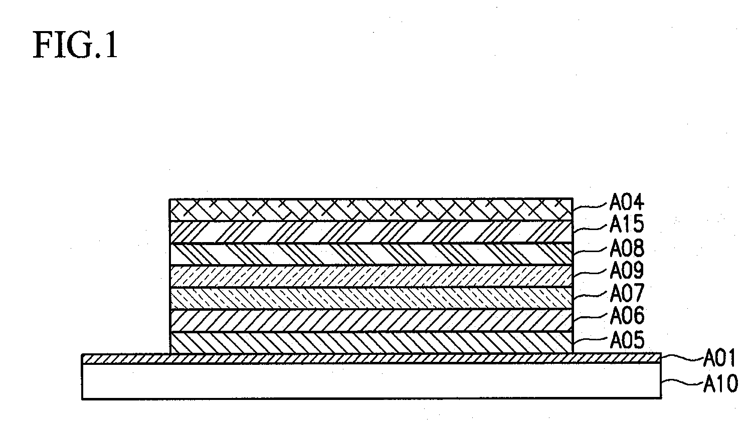
[0071]ITO electrodes, which were used as the first anode and the second anode, were disposed in the upper and lower surfaces of a transparent glass substrate at a thickness of 1800 Å. To fabricate the first element, m-MTDATA was formed as the first hole injection layer at a thickness of 600 Å, and NPB was formed as the first hole transport layer at a thickness of 150 Å on the first anode.

[0072]The first electroluminescent layer was formed at a thickness of 300 Å by co-depositing Alq3 as the light emitting host and DCM as a dopant on the upper part of the first hole transport layer. The content of Alq3 was 95 wt %, and the content of DCM was 5 wt %.

[0073]Subsequently, the fabrication of the first element was completed by disposing Alq3 at a thickness of 300 Å as the first electron transport layer, LiF at a thickness of 10 Å as the first electron injection layer, and Al at a thickness of 2000 Å as the reflective cathode, sequentially.

[0074]A transparent cathode having optical transpar...

example 2

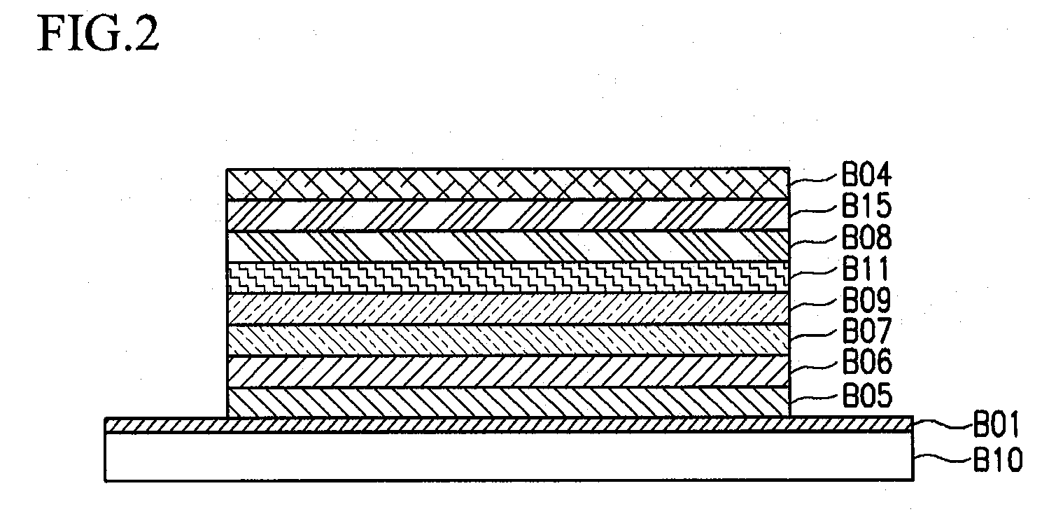
[0080]ITO electrodes, which were used as the first anode and the second anode, were disposed on the upper and lower surfaces of a transparent glass substrate at a thickness of 1800 Å. To fabricate the first element, m-MTDATA was formed as the first hole injection layer at a thickness of 600 Å, and NPB was formed as the first hole transport layer at a thickness of 150 Å on the first anode.

[0081]DPVBi was formed as a blue electroluminescent layer on top of the first hole transport layer at a thickness of 200 Å, and a 95 wt % Alq3 host and a 5 wt % DCM dopant were co-deposited as a red electroluminescent layer at a thickness of 150 Å.

[0082]Subsequently, the fabrication of the first element was completed by disposing Alq3 at a thickness of 250 Å as the first electron transport layer, LiF at a thickness of 10 Å as the first electron injection layer, and Al at a thickness of 2000 Å as the reflective cathode, sequentially.

[0083]A transparent cathode having an optical transparency of over 8...


PUM


Abstract

Provided is a white light emitting organic electroluminescent device, which includes a transparent substrate, a first element, and a second element. The first element includes a first anode, a first element organic layer, and a reflective cathode sequentially disposed on a first substrate of the transparent substrate. The second element includes a second anode, a second element organic layer, and a transparent or translucent cathode sequentially disposed on a second surface of the transparent substrate. The white light emitting organic electroluminescent device of the present invention can eliminate the color coordinates shift phenomenon of white light that occurs in a conventional three primary color white light organic electroluminescent device. Since the aging effect caused by heat generated from light emission is reduced by dividing electroluminescent layers, the electroluminescent device can have a long lifespan.

Description

TECHNICAL FIELD[0001]The present invention relates to a white light emitting organic electroluminescent device. More particularly, the present invention relates to a high efficiency white light emitting organic electroluminescent device that includes at least two color electroluminescent layers combined in parallel.BACKGROUND ART[0002]Organic electroluminescent devices have advantages that they do not require a backlight because they emit light on their own, differently from a liquid crystal display (LCD), and they can be manufactured to have a thickness of less than several nanometers to be used as thin and light display devices.[0003]The organic electroluminescent devices are also drawing attention as next-generation display devices because the structure and manufacturing process of the organic electroluminescent devices are relatively simple and the production cost is low.[0004]Particularly, since the organic electroluminescent devices have high luminous efficiency and low drivin...

Claims


Application Information

Patent Timeline
Patent Type & Authority Applications(United States)
IPC IPC(8): H01J1/62
CPCH01L27/3209H01L51/005H05B33/22H01L51/0065H01L51/5036H01L51/0059H10K59/32H10K85/60H10K85/631H10K85/653H10K50/125H05B33/12
Inventor PARK, HO-CHEOLCHOI, CHEOL-KYUPARK, JONG-WOOKYANG, JI-BUM
Owner DOOSAN CORP
Why Eureka
Try Eureka