Programmable Microphone

a programmable microphone and microphone body technology, applied in the direction of transducer details, electrostatic transducer microphones, electrical transducers, etc., can solve the problems of reducing the probability of fake programming signals being received and used to select modes, affecting the performance of electronic circuits, and affecting the operation of the microphone. , to achieve the effect of avoiding unintended or faulty selection of wrong modes, reducing the probability of fake programming signals and reducing the likelihood of a programming

Active Publication Date: 2009-01-01
ANALOG DEVICES INC
View PDF9 Cites 103 Cited by
  • Summary
  • Abstract
  • Description
  • Claims
  • Application Information

AI Technical Summary

Benefits of technology

[0055]In general it is noted that selecting a different mode than desired could severely degrade the performance of the electronic circuit. In an embodiment, the semiconductor die comprises a mode controller configured to receive programming instructions carried by a programming signal and to provide the control signal to the active device; and a mode detector which is configured to receive a mode select signal and to enable or disable the mode controller in response to the mode select signal. Thereby the likelihood that a fake programming signal is received and used to select mode is reduced so as to avoid unintended or faulty selection of a wrong mode. When only a limited number of pads are available and the programming signal is received via a pad that serves to interface another signal (e.g. an output signal) when the circuit is in a normal mode of operation (when mode controller is disabled), the enable signal can serve to alter which circuits that are operativel

Problems solved by technology

However, the disclosed solutions have introduced at least one additional and unfortunate noise source which is disregarded.
This may appear to be a small drawback in the light of providing adaptation to different acoustic situations, but this unfortunate source will contribute to non-repairable imperfections in the microphone signal, making it more difficult to arrive at a high performance microphone.
This is inappropriate in that the sensitivity is thus determined by a capacitor on the semiconductor die and a capacitor external to the semiconductor die.
This makes it almost impossible to obtain a desired value of sensitivity precisely—at least with reasonable yield values.
It would in general not be

Method used


Image

  • Programmable Microphone
  • Programmable Microphone
  • Programmable Microphone

Examples


Embodiment Construction

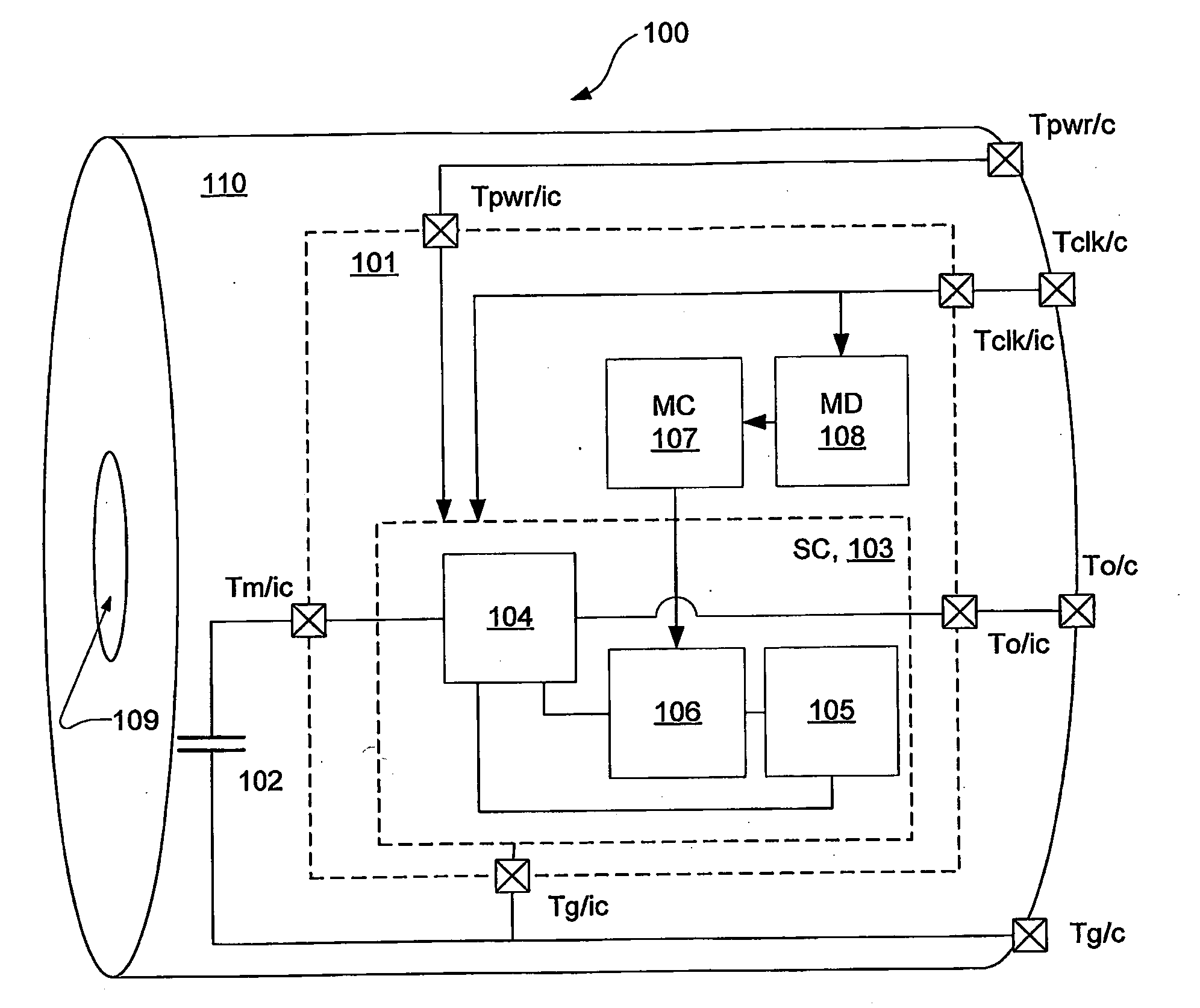
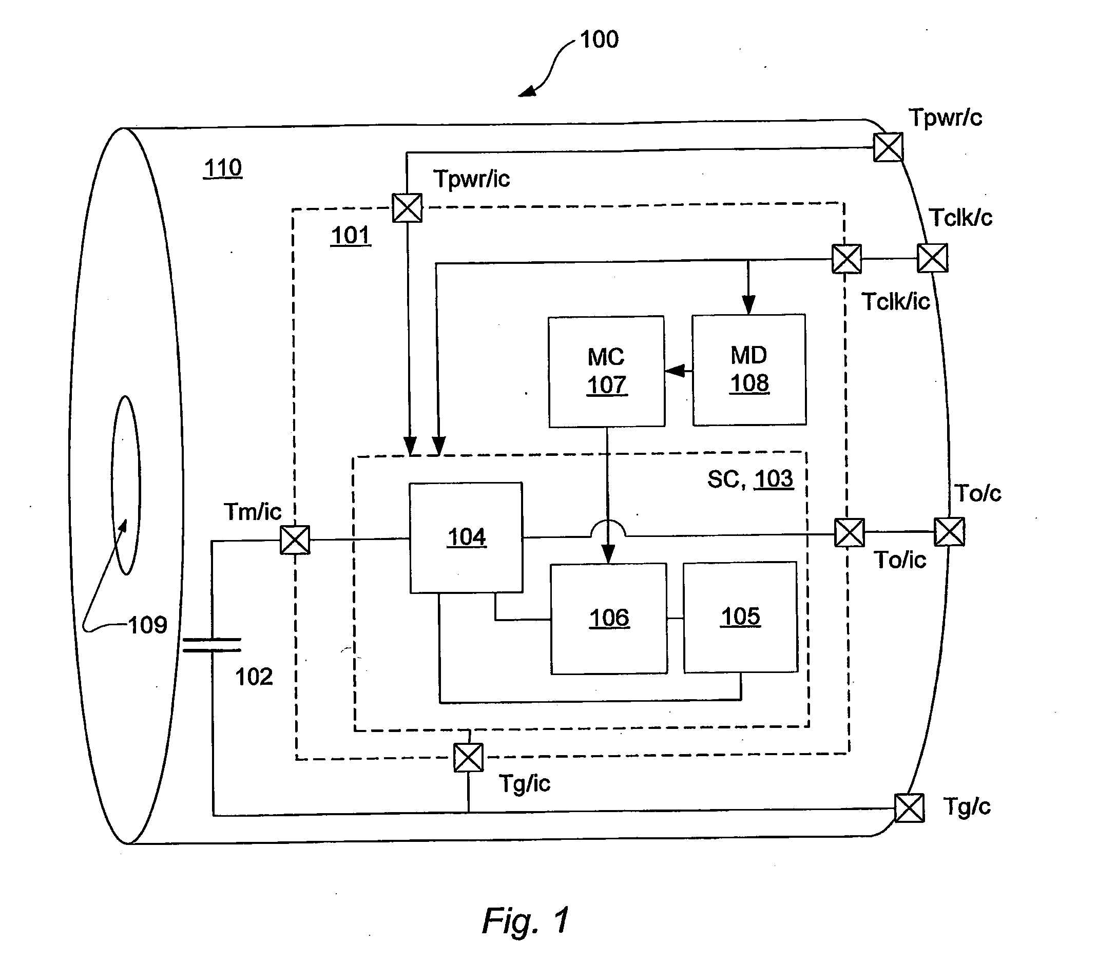
[0085]FIG. 1 shows a microphone configured to be operated in a selectable mode. The microphone 100 comprises a capsule or housing 110 that accommodates a capacitor microphone 102 and an semiconductor die 101 and connector terminals Tpwr / c, Tclk / c, To / c and Tg / c. The capacitor microphone 102 has a membrane member that moves relative to a second member (e.g. a so-called back plate) in response to a sound pressure on the membrane. The housing comprises an opening 109 for passage of sound. The capacitor microphone is coupled to the semiconductor die via terminals on the IC. The terminals are designated Tm / ic and Tg / ic, where the slash ‘ic’ designates that the terminals are located on the semiconductor substrate or integrated circuit, IC. Via the terminal Tm / ic a microphone capacitor signal provided by movements of the membrane is input to the IC. The second member is coupled to a ground reference which is coupled to the IC via terminal Tg / ic and to an external circuit via the terminal T...


PUM


Abstract

A semiconductor die with an integrated electronic circuit, configured so as to be mounted in a housing with a capacitive transducer e.g. a microphone. A first circuit is configured to receive an input signal from the transducer at an input node and to provide an output signal at a pad of the semiconductor die. The integrated electronic circuit comprises an active switch device with a control input, coupled to a pad of the semiconductor die, to operatively engage or disengage a second circuit interconnected with the first circuit so as to operate the integrated electronic circuit in a mode selected by the control input. That is, a programmable or controllable transducer. The second circuit is interconnected with the first circuit so as to be separate from the input node. Thereby less noise is induced, a more precise control of the circuit is obtainable and more advanced control options are possible.

Description

BACKGROUND[0001]The demand for microphones for mobile equipment such as mobile telephones, headsets and cameras tends to follow the growing demand for mobile equipment—for instance mobile telephones.[0002]The demand has for many years been rather simple in that the demand was for microphones with extremely low costs and for microphones suitable for production in very high volumes. The performance of such microphones was comparable from one manufacturer to another and was at a level comparable to that of telephony systems. In recent years, however, the demand has changed to also be for microphones with a performance above that of telephony systems. Today there appears to be a trend in the demand heading towards so-called high-fidelity (hi-fi) quality.[0003]Use of integrated digital processors, with ever increasing performance, in the different types of mobile equipment has also brought attention to the performance of the more peripheral links of the signal processing chain from pick-...

Claims


Application Information

Patent Timeline
IPC IPC(8): H04R3/00
CPCH04R1/005H04R3/00H04R19/04
Inventor SHAJAAN, MOHAMMADTHOMSEN, HENRIKGAARDE HENRIKSEN, JENS JORGEFUERST, CLAUS ERDMANN
Owner ANALOG DEVICES INC
Why Eureka
Try Eureka