Method for smoothing cementitious slurry in the production of structural cementitious panels

a technology of structural cementitious panels and cementitious slurry, which is applied in the field of smoothing, can solve the problems of increasing poor strength development of panels, and low panel strength, and achieves the effects of reducing the processing time of panel production equipment and processing time, reducing pock marks and grooves, and reducing the production cost of cementitious panels

Active Publication Date: 2009-01-01
UNITED STATES GYPSUM CO
View PDF35 Cites 18 Cited by
  • Summary
  • Abstract
  • Description
  • Claims
  • Application Information

AI Technical Summary

Benefits of technology

[0030]Typically a pneumatic vibrator is mounted on the top surface of the smooth plate for imparting vibration to the stiffening member which will cause the smoothing surface of the plate to vibrate while in use, thereby aiding the smoothing of the panel surface to remove pock marks and grooves. For example, the vibrator may be mounted on the stiffening member to impart vibration to the entire surface in contact with the newly formed panel surface.
[0031]The smoothing device with its pivoting mounting is designed to have the downstream end portion of the plate “float” up and down over the surface of the freshly formed cementitious material and reinforcing fiber slurry. Thus, only a low pre-determined pressure is exerted on the top surface of the slurry ...

Problems solved by technology

Due to non-uniform distribution the reinforcing properties resulting due to the fiber-matrix interaction vary through the thickness of the board, depending on the thickness of each board layer.
When insufficient penetration of the slurry through the fiber network occurs, poor bonding between the fibers and the matrix results, causing low panel strength.
Also, in some cases when distinct layering of slurry and fibers occurs, improper bonding and inefficient distribution of fibers causes poor panel strength development.
They are not used in the process of depositing gypsum and aggregate slurry over loose cho...

Method used


Image

  • Method for smoothing cementitious slurry in the production of structural cementitious panels
  • Method for smoothing cementitious slurry in the production of structural cementitious panels
  • Method for smoothing cementitious slurry in the production of structural cementitious panels

Examples


examples

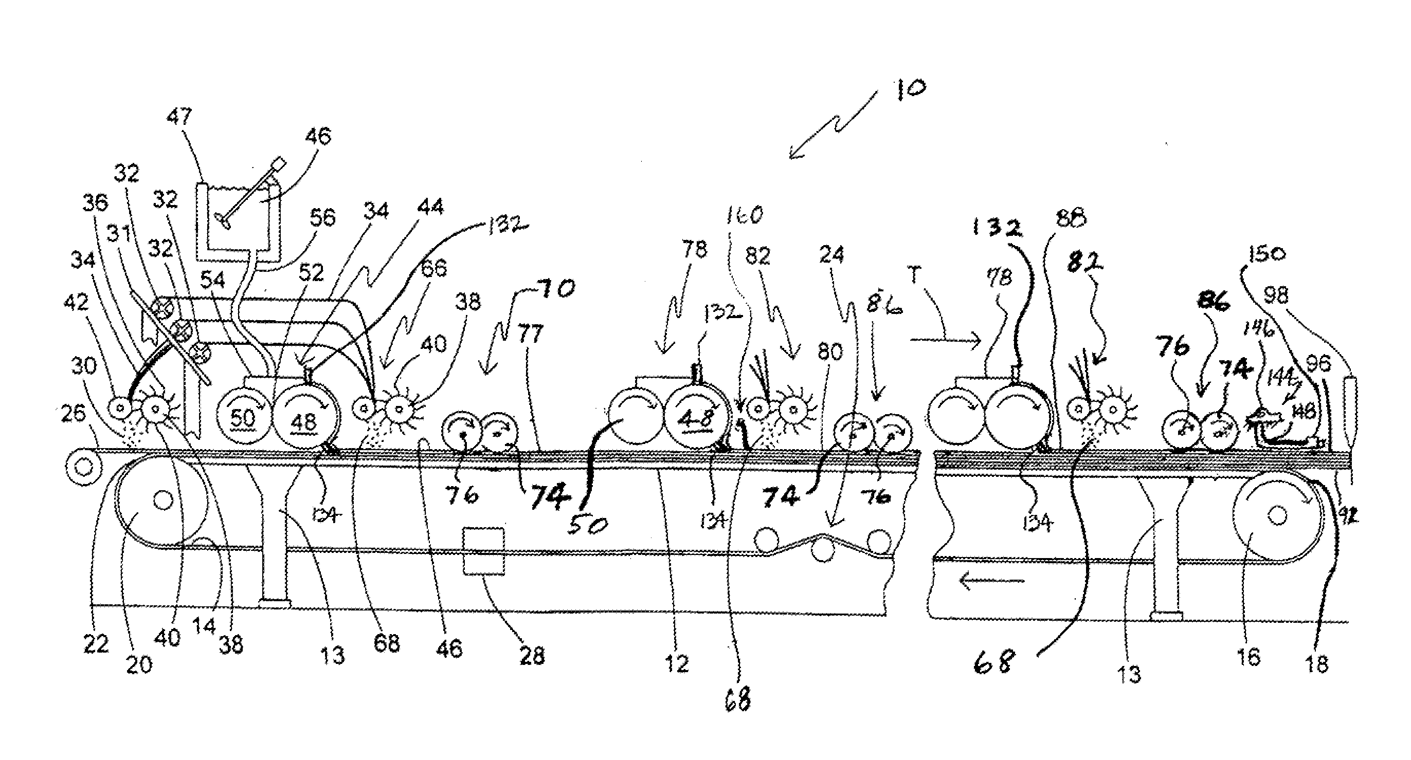
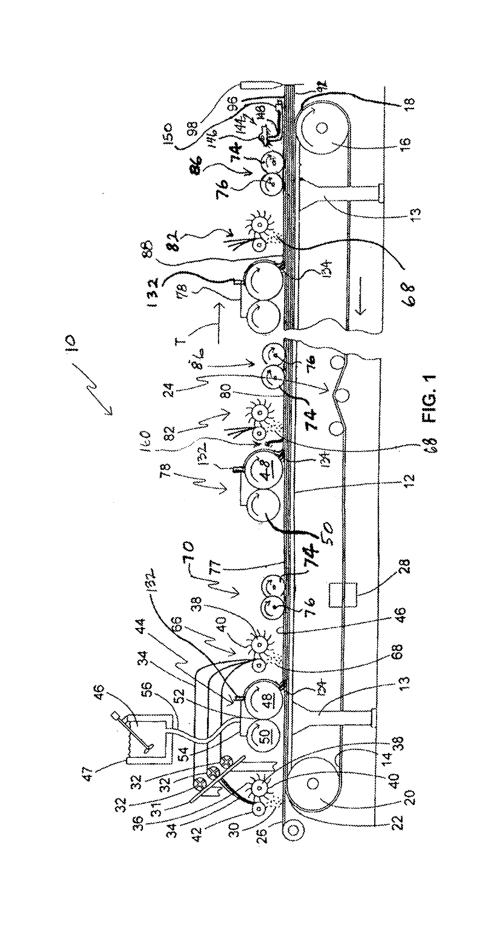
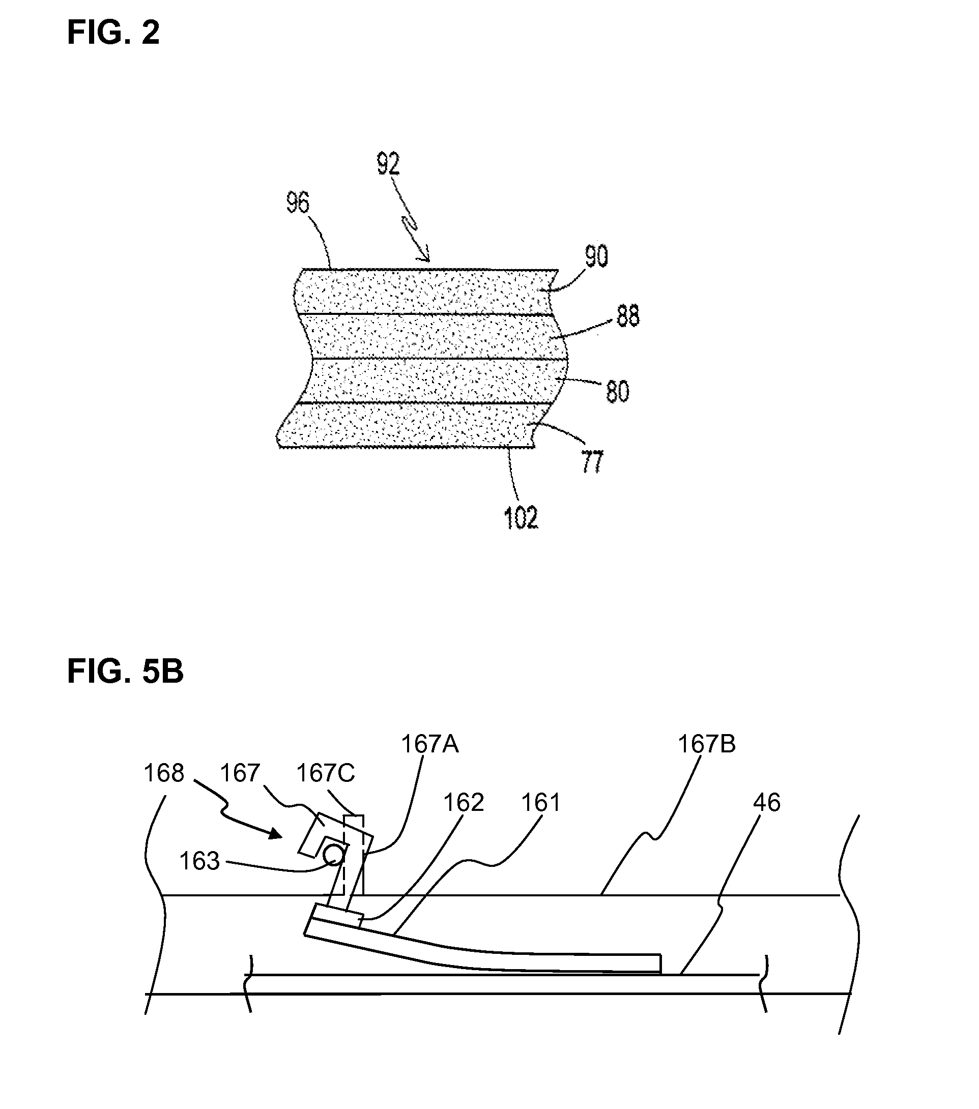
[0221]An experimental evaluation of the effectiveness of the present slurry smoothing device was conducted. This objective was achieved by manufacturing panels on a commercial production line similar to that shown in FIG. 6 by building up multiple distinct fiber and slurry layers to produce panels of design thickness. The performance of the proposed slurry smoothing device after the second slurry headbox station and before the next fiber chopper station and second embedment device stations, as shown in FIG. 6, was compared with the conventional production line in which only one floating screed plate or shroud is used after the final embedment station in a multiple slurry and chopped fiber layer, as disclosed in co-pending U.S. patent application Ser. No. 11 / 555,661 filed Nov. 1, 2006. The results of large size defects (FIGS. 8 and 9) as well as smaller size but still significant defects from smaller air holes (FIG. 10), compared to the essentially defect free panel of the invention ...

example formulation

[0222]Standard SCP formulation shown in Tables A and B, above, were used to manufacture all panels. The reactive powder used was a blend of ASTM Type III Portland cement, alpha hemihydrate, silica fume and lime. Hollow ceramic spheres were used as lightweight fillers to reduce the material / panel density. Polynapthalene sulfonate type superplasticizer was used as the water-reducing admixture. Alkali-resistant glass fibers chopped from a continuous roving with designation NEG ARG-103 (procured from Nippon Electric Glass Company, North America) were used as the reinforcing fibers. For this continuous roving, the roving tex was 2500 and the strand tex was 80. Each fiber strand was an assemblage of 200 alkali-resistant glass fiber monofilaments. The length of the fibers used was 40 mm.

[0223]The SCP slurry used in the practice of this invention has a density of about 78 to 82 pounds per cubic foot compared to a gypsum board slurry used in typical fiberglass reinforced gypsum board of abou...

example results

[0227]A fiber embedment device must effectively embed a distinct layer of fiber network into a distinct layer of slurry for producing fiber reinforced cementitious panels.

[0228]To have desirable product, USG's FORTACRETE Product Bulletin 14-07-001 at page 4 provides the current “VISUAL APPEARANCE SPECIFICATIONS and testing frequency for SCP panel production online observations for slurry spread:

Slurry Spread Definition: Uniform and continuous slurry headbox output visually apparent in the field of the board. No visually noticeable unusual slurry distribution or patterns should be present in the field or edges.

Reject Specification Panels containing such characteristics must be put on hold and must be released / rejected based on the results from the quality control testing on the final panel.”

[0229]The above description of the visual testing refers to unusual slurry distribution including the times when the slurry curtain coming off the doctor blade “breaks” for any reason and a long s...


PUM

PropertyMeasurementUnit
Timeaaaaaaaaaa
Pressureaaaaaaaaaa
Pressureaaaaaaaaaa

Abstract

A vibrating smoothing device or plate transverse to a direction of travel of deposited gypsum-cementitious slurry and embedded chopped fibers. The plate is used to smooth the top surface of the slurry panel as it exits a first fiber embedment station and a second slurry depositing station before passing through a second fiber embedment station of a structural cementitious panel production line to remove grooves and other non-uniform surface imperfections to have the slurry cover the embedded fibers The plate is designed to float over the surface of the formed slurry without tearing or otherwise damaging the surface of the heavily fiber reinforced surface layers of the formed slurry before it sets. The vibrating plate is pivotally mounted on the web production line so it can float over the panel surface during use, but be raised off the line when not in use.

Description

CROSS REFERENCE TO RELATED APPLICATIONS[0001]This application is related to co-pending patent applications:[0002]U.S. Pat. No. 6,986,812 entitled SLURRY FEED APPARATUS FOR FIBER-REINFORCED STRUCTURAL CEMENTITIOUS PANEL PRODUCTION, issued on Jan. 17, 2006;[0003]U.S. patent application Ser. No. 10 / 666,294 entitled APPARATUS FOR PRODUCING HIGH STRENGTH FIBER-REINFORCED STRUCTURAL CEMENTITIOUS PANELS, filed Sep. 18, 2003;[0004]U.S. patent application Ser. No. 11 / 555,647, entitled PROCESS AND APPARATUS FOR FEEDING CEMENTITIOUS SLURRY FOR FIBER-REINFORCED STRUCTURAL CEMENT PANELS, filed Nov. 1, 2006;[0005]U.S. patent application Ser. No. 11 / 555,655, entitled METHOD FOR WET MIXING CEMENTITIOUS SLURRY FOR FIBER-REINFORCED STRUCTURAL CEMENT PANELS, filed Nov. 1, 2006;[0006]U.S. patent application Ser. No. 11 / 555,661, entitled PANEL SMOOTHING PROCESS AND APPARATUS FOR FORMING A SMOOTH CONTINUOUS SURFACE ON FIBER-REINFORCED STRUCTURAL CEMENT PANELS, filed Nov. 1, 2006;[0007]U.S. patent applica...

Claims


Application Information

Patent Timeline
IPC IPC(8): B05D1/00
CPCB28B1/08B28B1/29B28B19/0092B28B23/0006C04B28/14C04B2111/00612C04B7/02C04B14/185C04B14/24C04B14/301C04B14/42C04B18/082C04B18/146C04B22/064C04B24/226C04B40/02Y02W30/91
Inventor JONES, JOHN G.
Owner UNITED STATES GYPSUM CO
Why Eureka
Try Eureka