Method for manufacturing organic el display and organic el display
a technology of organic el and manufacturing method, which is applied in the manufacture of electrode systems, discharge tubes luminescent screens, electric discharge tubes/lamps, etc., can solve the problems of plasma generation imposing electric damage on electric circuits, film roughening on the surface, and possible white turbidity roughening, etc., to achieve the effect of reducing the generation of white turbidity, enhancing manufacturing quality, and manufacturing yield
- Summary
- Abstract
- Description
- Claims
- Application Information
AI Technical Summary
Benefits of technology
Problems solved by technology
Method used
Image
Examples
first embodiment
[0034]Initially, the schematic structure of an organic EL display will be described below.
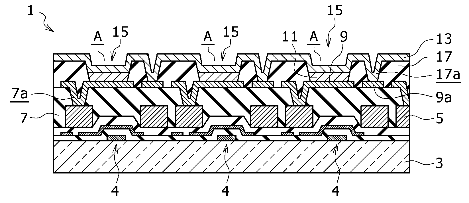
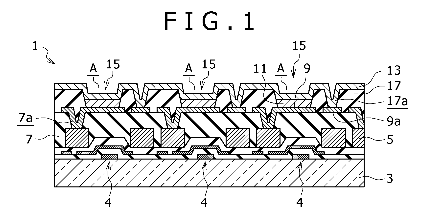
[0035]FIG. 1 is a major-part sectional view showing one example of the schematic structure of the display area of the organic EL display. In this example, the schematic structure of an active-matrix organic EL display in which organic EL elements are arranged as light-emitting elements is shown.
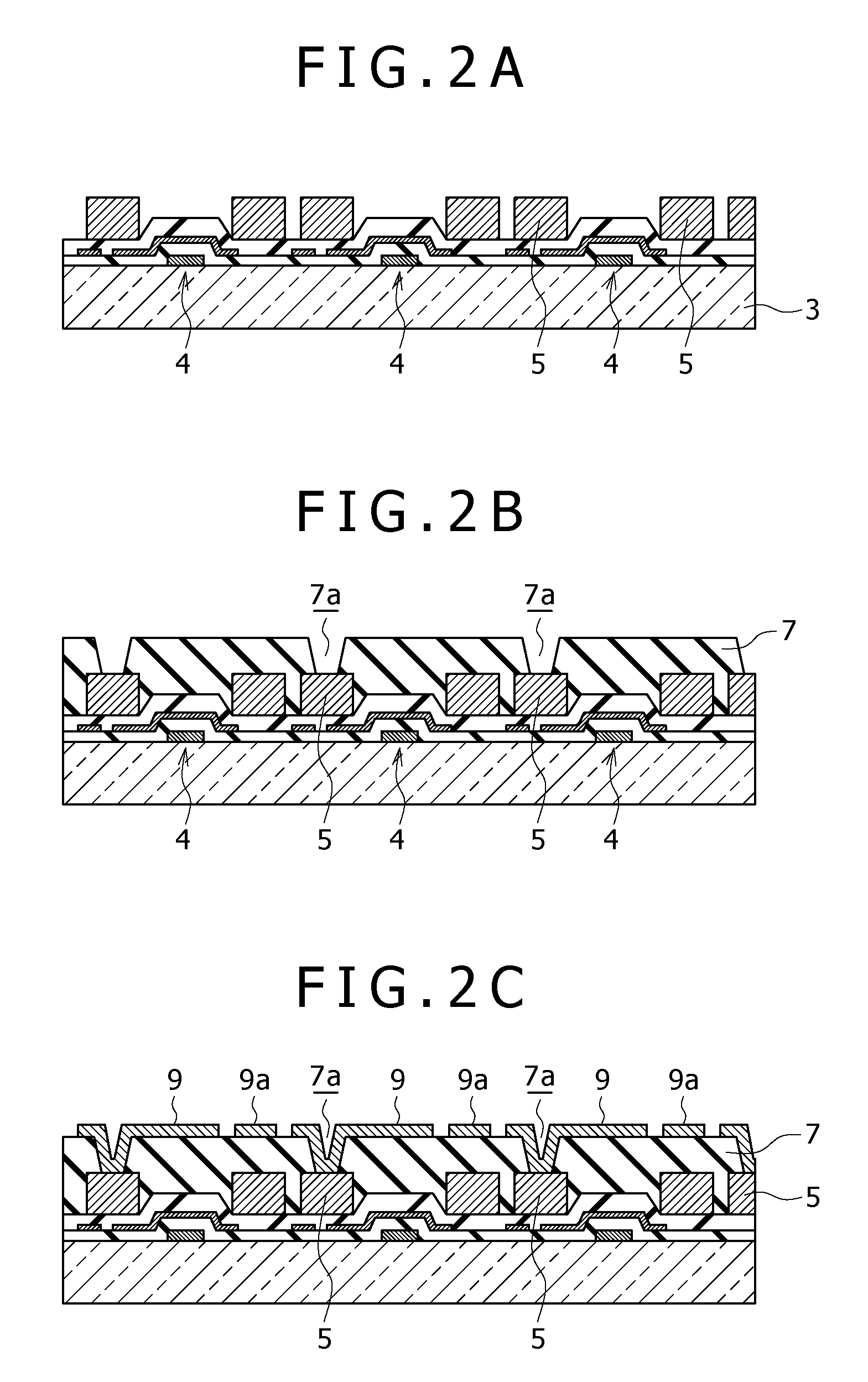
[0036]An organic EL display 1 of this example includes TFTs 4 in the respective pixels over a substrate 3. Over the substrate 3 on which the TFTs 4 are formed, interconnects 5 connected to the sources and drains of the TFTs 4 are formed, and a planarization insulating film 7 is provided to cover these interconnects 5. The TFT 4 is not limited to the bottom-gate TFT shown in FIG. 1 but may be a top-gate TFT. The gate electrodes of the TFTs 4 are connected to a scan circuit.
[0037]In each of pixel apertures A over this planarization insulating film 7, an organic EL element 15 arising from stacking of a lowe...
second embodiment
[0092]FIG. 6 is an explanatory diagram showing another example of a manufacturing step for an organic EL display according to a second embodiment of the present invention.
[0093]In the manufacturing of the organic EL display of this example, a metal layer (composed of e.g. a TiAl-based alloy) serving as the interconnect 5 is deposited as a pattern on the substrate 3, and the planarization insulating film 7 is deposited thereon. Furthermore, the auxiliary interconnect 9a is formed, and the upper electrode 13 is formed on the top surface side of the auxiliary interconnect 9a with the intermediary of the insulating film 17. It will be possible that the upper electrode 13 is formed of e.g. a blanket film of magnesium-silver (MgAg). Moreover, the protective film 10 for protecting the entire substrate is deposited by CVD to cover the whole of the top surface side of these layers.
[0094]However, the protective film 10 deposited by CVD will be charged due to plasma treatment. Such charging sh...
third embodiment
[0102]FIG. 8 is a major-part sectional view showing another example of the schematic structure of the display area of an organic EL display.
[0103]In the organic EL display of this example, a multilayer structure 30 obtained by sequentially stacking a cathode auxiliary interconnect 31, an interlayer insulating film 32, a source metal layer 33, a planarization film 34, an ITO layer 35, and a bank layer 36 is formed on the substrate 3. This multilayer structure 30 is formed on the light-emission area 21. A cathode 37 is deposited on the multilayer structure 30. The interlayer insulating film 32 electrically isolates data lines Idat and scan lines Vsel from the cathode auxiliary interconnect 31. On the interlayer insulating film 32, the source metal layer 33 patterned in the same step as that for the data lines Idat and the scan lines Vsel is formed into an island shape. The source metal layer 33 is electrically connected to the cathode auxiliary interconnect 31 via contact holes h5 ope...
PUM
 Abstract
Description
Claims
Application Information
 - R&D
- Intellectual Property
- Life Sciences
- Materials
- Tech Scout
- Unparalleled Data Quality
- Higher Quality Content
- 60% Fewer Hallucinations
Browse by: Latest US Patents, China's latest patents, Technical Efficacy Thesaurus, Application Domain, Technology Topic, Popular Technical Reports.
© 2025 PatSnap. All rights reserved.Legal|Privacy policy|Modern Slavery Act Transparency Statement|Sitemap|About US| Contact US: help@patsnap.com


