Glass Processing Method Using Laser and Processing Device

a glass and laser technology, applied in the field of laser processing methods and processing devices, can solve the problems of inability to easily control the shape of the holes formed in the glass by laser irradiation with good reproducibility, and the fundamental wave cannot easily condense into a small spot, etc., to achieve the effect of reducing glass deformation, large numerical aperture, and easy variation of the size of the hol

Inactive Publication Date: 2009-01-15
NIPPON SHEET GLASS CO LTD
View PDF7 Cites 124 Cited by
  • Summary
  • Abstract
  • Description
  • Claims
  • Application Information

AI Technical Summary

Benefits of technology

[0009]In a method of the present invention, a predetermined laser pulse having a wavelength of 535 nm or less is condensed through a predetermined lens, and glass having a predetermined absorption coefficient is irradiated with the laser pulse to form an altered portion. The glass then is processed by etching the altered portion. A method of the present invention can use the harmonic of a Nd:YAG laser, and therefore allows the glass to be processed using an inexpensive device, compared with traditional methods using the femtosecond laser. Further, a method of the present invention can suppress glass deformation (such as generation of debris or cracking) in portions of the glass subjected to the process, and forms more uniformly shaped holes compared with traditional methods that process glass solely by irradiation with a laser pulse.
[0010]Further, in a processing method of the present invention, the L/D ratio of focal length L to beam diameter D is set to a value equal to or less than a predet

Problems solved by technology

In the Nd:YAG laser, however, the fundamental wave cannot easily condense into a small spot.
It is accordingly difficult to form fine holes by irradiation with the Nd:YAG laser.
Further, the shape of the holes formed in the glass by the laser irradiation cannot be controlled easily with good reproducib

Method used


Image

  • Glass Processing Method Using Laser and Processing Device
  • Glass Processing Method Using Laser and Processing Device
  • Glass Processing Method Using Laser and Processing Device

Examples


example 1

[0055]The following will describe an example of processing a glass plate made of titanium silicate glass (thickness: 0.3 mm; absorption coefficient at 355 nm: 8 cm−1). The percentages of the glass components are shown in Table 2.

TABLE 2ExamplesComparative1, 3, 524example 1Glass typeTitaniumTitaniumSilicateSoda-limePYREXsilicateComponentsSiO237.572.082.749.6(mol %)B2O312.5—11.6—TiO225.0——14.9Al2O3—0.91.419.8Na2O25.012.73.5—K2O——0.8—MgO—6.0—14.9CaO—8.4——CeO2———0.8Total100100100100

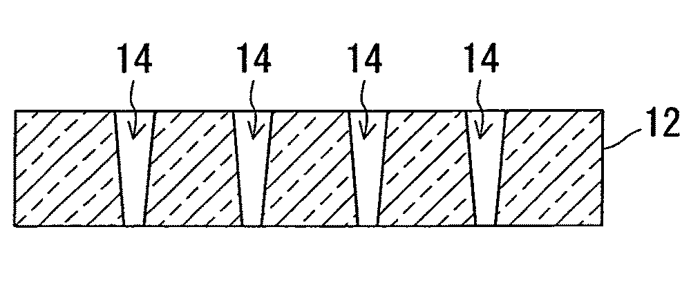
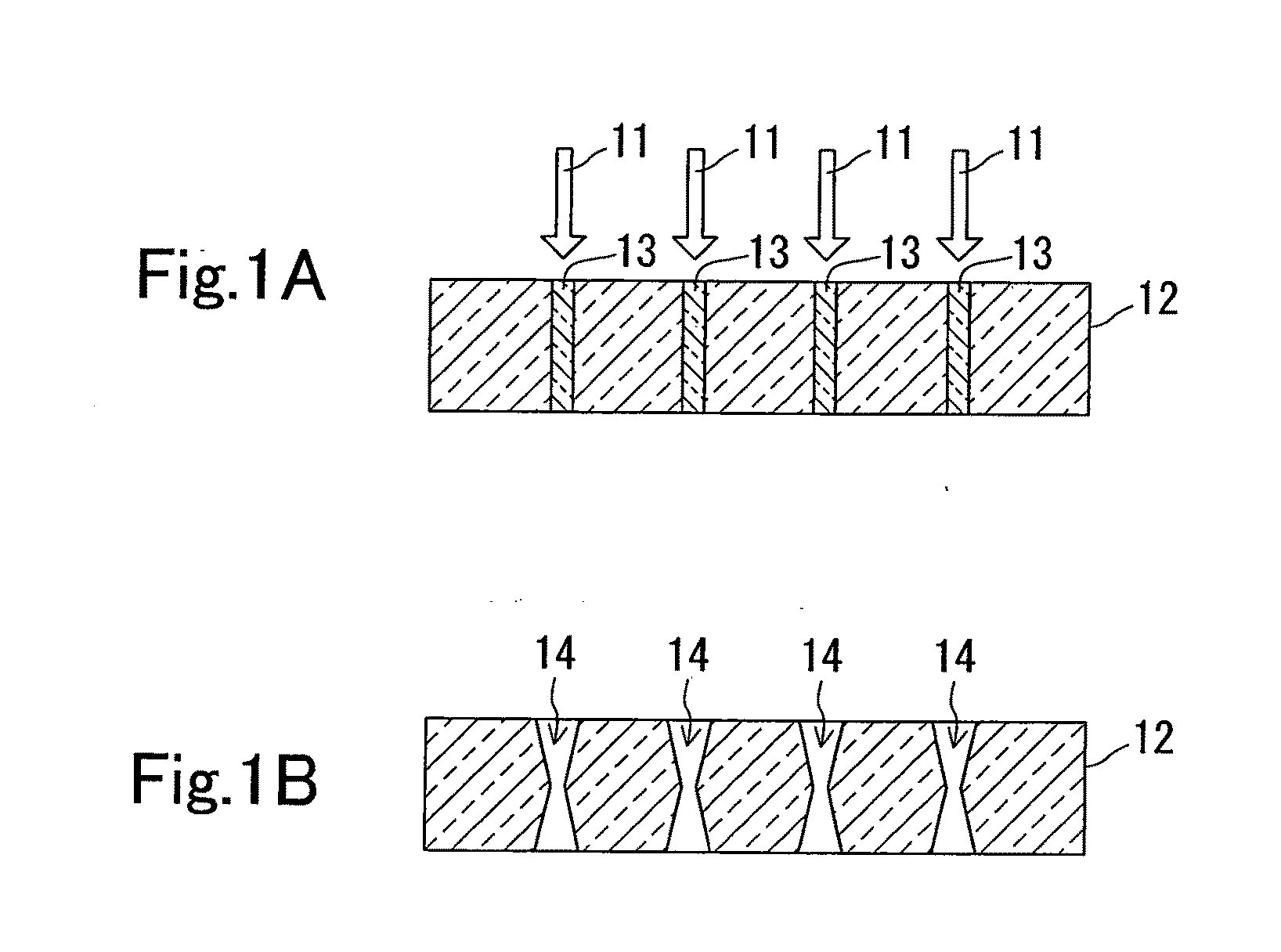
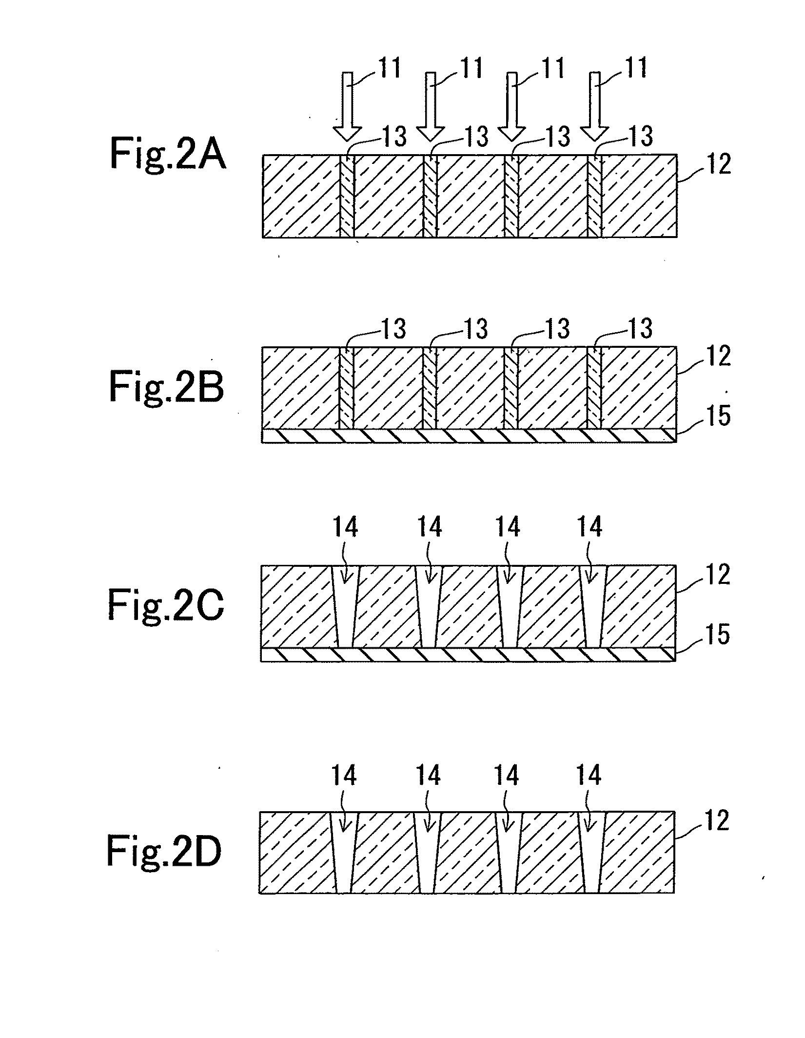
[0056]As the laser, a high repetition pulsed laser (wavelength: 355 nm; repetition frequency: 10 kHz) emitted from a Nd:YAG laser device (210S-UV, LightWave) was used. The laser pulse emitted from the laser device (pulse width: 9 ns; power: 370 mW; beam diameter: 1 mm) was expanded thirty-six times with a beam expander, narrowed by an aperture 14 mm in diameter, and condensed inside the glass plate with an fθ lens having a focal length of 160 mm. The diameter of the beam incident on the lens was 14 mm. The la...

example 2

[0063]The following will describe an example of processing a glass plate made of soda-lime glass (thickness: 0.41 mm; absorption coefficient at 355 nm: 0.3 cm−1). The percentages of the glass components are shown in Table 2.

[0064]As the laser, a high repetition pulsed laser (wavelength: 355 nm; repetition frequency: 20 kHz) emitted from a Nd:YAG laser device (Photonics Industries) was used. The laser pulse emitted from the laser device (pulse width: 24 ns; power: 450 mW; beam diameter: 1 mm) was expanded six times with a beam expander, and condensed inside the glass plate with an fθ lens having a focal length of 100 mm. The diameter of the beam incident on the lens was 6 mm. The laser beam was condensed at a position away from the top surface of the glass plate by a physical length of 0.20 mm. The laser beam was scanned at 1000 mm / s to prevent overlap of the irradiation pulses.

[0065]By the irradiation with the laser beam, recessed portions having a diameter of about 2 μm were formed...

example 3

[0068]The following will describe an example of processing a glass plate made of titanium silicate glass (thickness: 0.3 mm; absorption coefficient at 355 nm: 8 cm−1). The fractions of the glass components are shown in Table 2.

[0069]As the laser, a high repetition pulsed laser (wavelength: 355 nm; repetition frequency: 20 kHz) emitted from a Nd:YAG laser device (Photonics Industries) was used. The laser pulse emitted from the laser device (pulse width: 24 ns; power: 800 mW; beam diameter: 1 mm) was expanded six times with a beam expander, and condensed inside the glass plate with an fθ lens having a focal length of 100 mm. The diameter of the beam incident on the lens was 6 mm. The laser beam was condensed at a position away from the top surface of the glass plate by a physical length of 0.15 mm. The laser beam was scanned at 1000 mm / s to prevent overlap of the irradiation pulses.

[0070]By the irradiation with the laser beam, recessed portions having a diameter of about 9 μm and a de...


PUM

PropertyMeasurementUnit
Timeaaaaaaaaaa
Timeaaaaaaaaaa
Distanceaaaaaaaaaa

Abstract

A glass processing method comprising steps (i), (ii) carried out in the order mentioned. In step (i), a laser pulse (11) with a wavelength λ is condensed by a lens and is applied to a glass plate (12) to form an altered portion (13) at the portion, irradiated with a laser pulse (11), of the glass plate (12). In step (ii), the altered portion (13) is etched by using an etchant having an etching rate larger for the altered portion (13) than that for the glass plate (12). The laser beam used includes the following conditions: The pulse width of a laser pulse (11) ranges from ins to 200 ns, with a wavelength λ being up to 535 nm. The absorption coefficient of the glass plate (12) at a wavelength λ is up to 50 cm−1. A value obtained from a lens focal distance L (mm) divided by the beam diameter D (mm) of the laser pulse (11) when entering the lens is at least 7.

Description

TECHNICAL FIELD[0001]The present invention relates to a method and a device for processing glass using a laser.BACKGROUND ART[0002]Methods have been proposed for using a laser to form micro through-holes in glass. For example, JP2000-61667A discloses a method for forming holes in glass by irradiation with the fundamental wave (1064 nm) of a Nd:YAG laser. JP13 (2001)-105398A discloses a method that processes a substrate by etching, after altering portions of the substrate and forming microholes by irradiation of the altered portions with a laser beam. JP2001-105398A also discloses a method for forming microholes by first irradiating portions of a photosensitive glass plate with ultraviolet light to cause alteration and then irradiating the altered portions with a YAG laser.[0003]Methods that process glass using a ultrashort pulsed-laser also are disclosed (JP2004-351494A, JP16 (2004)-359475A). The processing methods disclosed in these publications use the femtosecond laser as the ult...

Claims


Application Information

Patent Timeline
IPC IPC(8): C03C17/22
CPCB23K26/0093B23K26/063B23K26/0807C03C23/0025B23K26/383B23K26/4075C03C15/00B23K26/18B23K26/40B23K26/0622B23K26/082B23K26/384B23K2103/50
Inventor KOYO, HIROTAKATSUNETOMO, KEIJISHOJIYA, MASANORI
Owner NIPPON SHEET GLASS CO LTD
Why Eureka
Try Eureka