

Three-dimensional image display apparatus
- Summary
- Abstract
- Description
- Claims
- Application Information
AI Technical Summary
Benefits of technology
Problems solved by technology
Method used
Image

Examples
working example 1
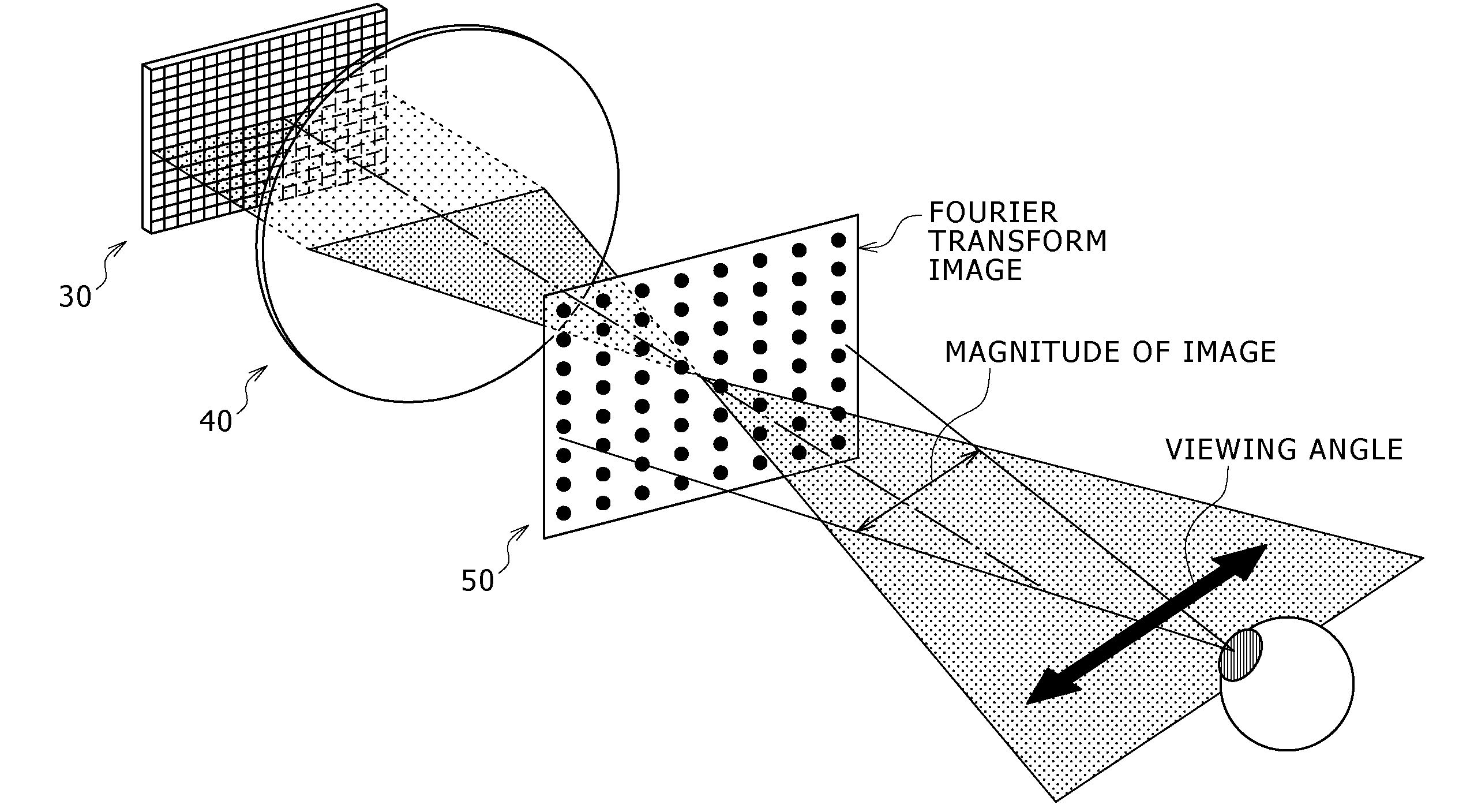
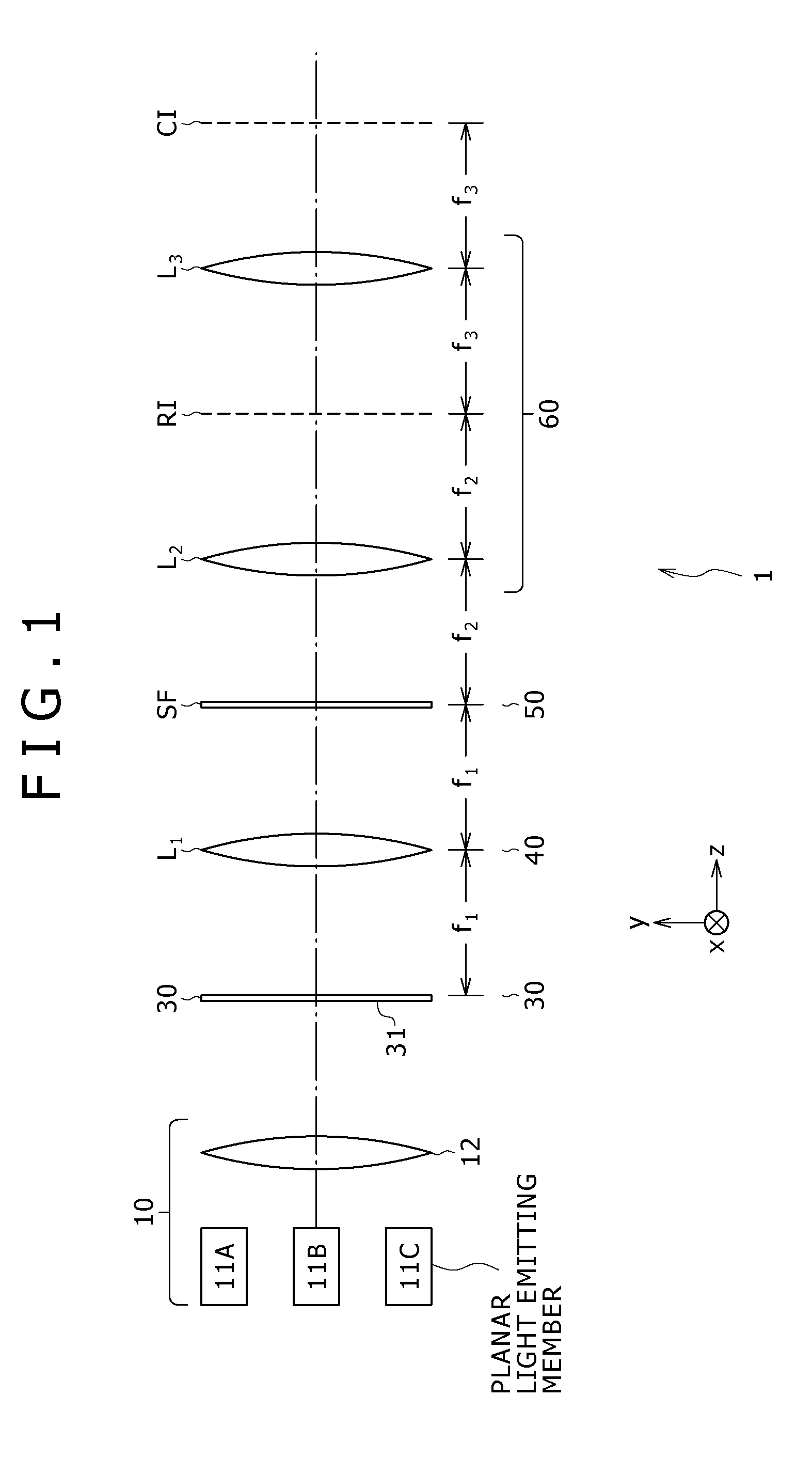
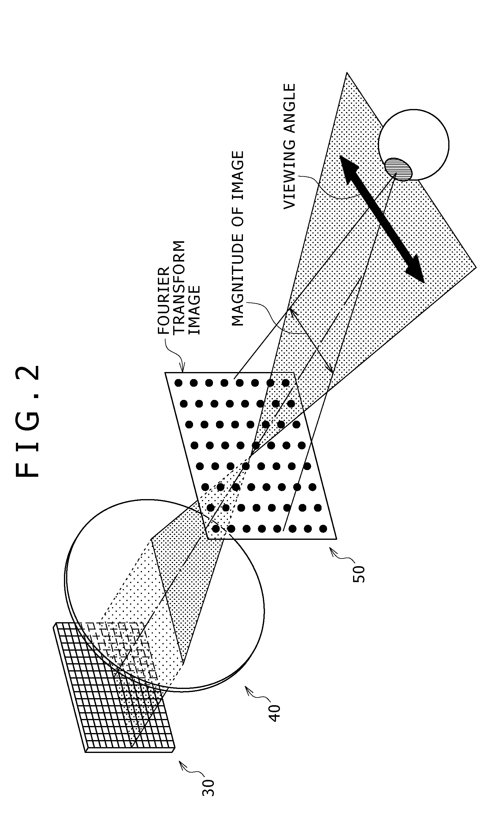
[0126]The working example 1 of the present invention is directed to three-dimensional image display apparatus according to first and second embodiments of the present invention. FIG. 1 shows the three-dimensional image display apparatus according to the working example 1 which displays a monochromatic image. It is to be noted that, in FIG. 1, the optical axis is set to a z axis, and Cartesian coordinates in a plane perpendicular to the z axis are taken on an x axis and a y axis. Further, the direction parallel to the x axis is represented as X direction and the direction parallel to the y axis is represented as Y direction. The X direction is taken, for example, as a horizontal direction of the three-dimensional image display apparatus, and the Y direction is taken, for example, as a vertical direction of the three-dimensional image display apparatus. Here, FIG. 1 is a schematic view showing the three-dimensional image display apparatus of the working example 1 on the yz plane. Also...
working example 2
[0170]The working example 2 is a modification to the working example 1. Different three-dimensional image display apparatus according to the working example 2 are shown in FIGS. 12 and 13. In the three-dimensional image display apparatus of the working example 1, the two-dimensional image forming apparatus 30 of the light transmission type is used. On the other hand, in the three-dimensional image display apparatus of the working example 2, optical modulation means or two-dimensional image forming apparatus 30A of the reflection type is used. The optical modulation means or two-dimensional image forming apparatus 30A of the reflection type may be, for example, a liquid crystal display apparatus of the reflection type.
[0171]Referring to FIG. 12, the two-dimensional image forming apparatus 30A of the working example 2 includes a beam splitter 70 provided on the z axis, that is, on the optical axis. The beam splitter 70 has a function of passing or reflecting light depending upon the p...
working example 3
[0173]The working example 3 is another modification to the working example 1 and includes a light detection section 80 for measuring the light intensity of light beams or illuminating light beams successively emitted from the planar light emitting members 11. More particularly, in the working example 3, the light detection section 80 is formed from a photodiode. FIG. 14 shows the three-dimensional image display apparatus of the working example 3 on the yz plane. Referring to FIG. 14, the three-dimensional image display apparatus of the working example 3 includes a light detection section 80 in the form of a photodiode, and a partially reflecting mirror or partial reflector 81 disposed between the light source 10 and the two-dimensional image forming apparatus 30, more particularly between the collimator lens 12 and the two-dimensional image forming apparatus 30. The partial reflector 81 extracts part of light incoming from the planar light emitting member 11 to the two-dimensional i...
PUM
 Abstract
Description
Claims
Application Information