Method of heat accumulation and heat accumulation system

Inactive Publication Date: 2009-01-22
PANASONIC CORP
View PDF7 Cites 17 Cited by
  • Summary
  • Abstract
  • Description
  • Claims
  • Application Information

AI Technical Summary

Benefits of technology

[0023]According to the present invention, when a thermal storage process is carried out using a hydrate, the second composition and water can be mixed together uniformly during the heat release process, and therefore, the quantity of thermal output can be increased. In addition, the thermal conductivity between the mixture of the second composition and water and

Problems solved by technology

However, the heat generated as a result is released into the external air.
Thus, according to the conventional sensible and latent heat storage techniques, the types of usable thermal storage materials are limited by the temperature of the heat source and a high thermal storage density

Method used


Image

  • Method of heat accumulation and heat accumulation system
  • Method of heat accumulation and heat accumulation system
  • Method of heat accumulation and heat accumulation system

Examples


embodiment 1

[0081]Hereinafter, a Thermal Storage Method as a First preferred embodiment of the present invention will be described with reference to the accompanying drawings.

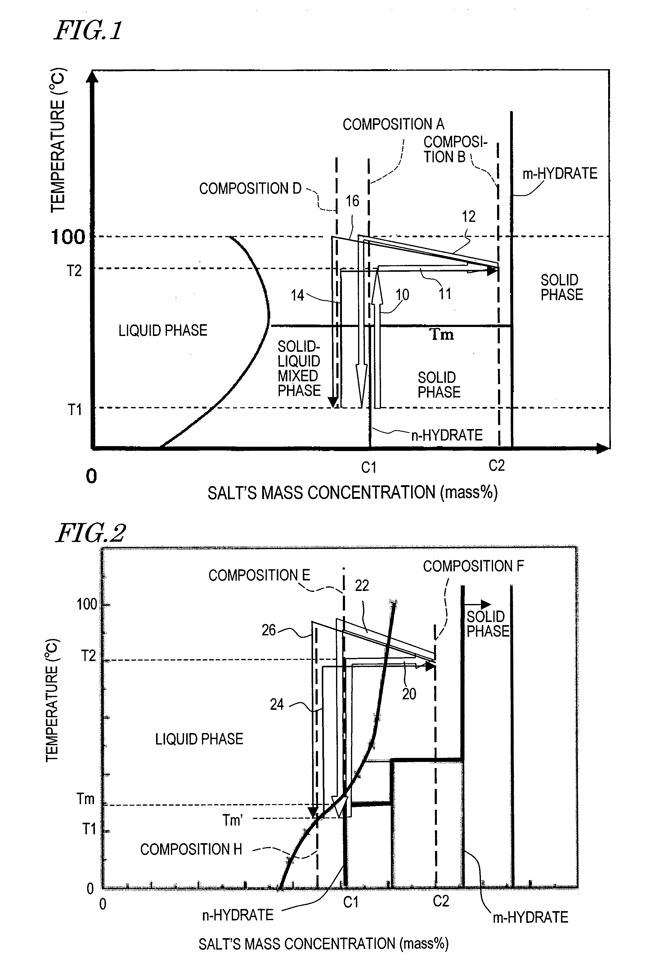
[0082]FIG. 1 illustrates an example of thermal storage and release processes according to this preferred embodiment. In FIG. 1, the abscissa represents the concentration of the composition and the ordinate represents the temperature, and a phase diagram, showing what phases are present in an inorganic salt and water, is shown.

[0083]In this example, Composition A (with an inorganic salt concentration c1) to be an n-hydrate in solid phase at a temperature T1 is used as the first composition. The temperature T1 may be equal to room temperature, for example.

[0084]In the thermal storage process, first, when the temperature of the n-hydrate is increased from the temperature T1 to a temperature T2, which is higher than the phase change temperature Tm, as indicated by the arrow 10, an m-hydrate in solid phase is produced through t...

embodiment 2

[0097]Hereinafter, a thermal storage method as a second preferred embodiment of the present invention will be described with reference to the accompanying drawings. This preferred embodiment is different from the preferred embodiment described above in that the first composition becomes the second composition by going through a simple liquid phase in the thermal storage process. More specifically, in the preferred embodiment described above, a solid-liquid mixed phase is produced by heating the first composition to the temperature T2 and the second composition is obtained by separating water from the first composition in the solid-liquid mixed phase. Meanwhile, according to this preferred embodiment, when the first composition is heated to the temperature T2, an aqueous solution is produced, and the second composition is obtained by separating water from that aqueous solution.

[0098]FIG. 2 illustrates an example of thermal storage and release processes according to this preferred emb...

example 1

[0137]Hereinafter, specific examples of a thermal storage method according to the present invention will be described with reference to the accompanying drawings.

[0138]In a first specific example of the present invention, using a hydrate including magnesium sulfate and water at a molar ratio of one to seven, thermal storage and heat release processes are carried out with the thermal storage system that has already been described with reference to FIGS. 10 and 11. FIG. 12 is a phase diagram of magnesium sulfate and water, where the thermal storage process of this specific example is indicated by the arrow 90.

[0139]First, magnesium sulfate heptahydrate is put as a first composition 91 into the thermal storage vessel 51. The temperature of the magnesium sulfate heptahydrate is supposed to be room temperature (of approximately 15° C.).

[0140]Next, a thermal storage process is carried out by obtaining a second composition 92 in solid-liquid mixed phase at approximately 80° C. from the mag...


PUM


Abstract

A thermal storage method according to the present invention includes the steps of: (A) putting a first composition A, including an n-hydrate (where n is a hydration number) of an inorganic salt in solid phase and having a phase change temperature Tm of 100° C. or less, in a thermal storage material container; (B) heating the first composition A to a temperature T2 that is higher than the phase change temperature Tm and removing water contained in the first composition A from the thermal storage material container, thereby obtaining a second composition B in which an m-hydrate (where m is also a hydration number and m<n) of the inorganic salt in solid phase and an aqueous solution of the inorganic salt are both included; (C) stopping removing the water from the thermal storage material container on sensing that the second composition B has been obtained; (D) reserving the second composition B; and (E) mixing the second composition B with water, thereby recovering at least a part of the heat that is stored in the second composition B.

Description

TECHNICAL FIELD[0001]The present invention relates to a method and system for thermal storage.BACKGROUND ART[0002]Various thermal storage techniques for conserving thermal energy have been used effectively to save energies. Meanwhile, recently, hot water supply units that use a CO2 heat pump or a fuel-cell cogeneration system (which will be referred to herein as a “fuel-cell cogene”) have attracted a lot of attention in the art. In order to reduce the sizes of those units and install them more efficiently, development of high-density thermal storage technology is awaited.[0003]Conventional thermal storage techniques are roughly classifiable into sensible heat storage, latent heat storage, and chemical heat storage techniques. According to the sensible and latent heat storage techniques, some loss such as heat exchange loss is inevitable in practice but there is no need to newly apply any thermal energy during the heat release process. That is why theoretically speaking, almost the s...

Claims


Application Information

Patent Timeline
IPC IPC(8): F28D15/00
CPCC09K5/063F28D20/02F28D20/021Y02E60/145F28D20/003Y02E60/142Y02E60/14
Inventor MORITA, YOSHIOSUZUKI, MOTOHIRO
Owner PANASONIC CORP
Why Eureka
Try Eureka