Hybrid composite including carbon nanotube and carbide-derived carbon, electron emitter including the hybrid composite, method of preparing the electron emitter, and electron emission device including the electron emitter

a hybrid composite and carbon nanotube technology, applied in the manufacture of electrode systems, conductors, electric discharge tubes/lamps, etc., can solve the problems of fiber-shaped materials, lack of uniformity and lifetime, and decreased electron emission performance, so as to prevent screen effects and ensure uniformity and long li

Inactive Publication Date: 2009-01-29
SAMSUNG SDI CO LTD
View PDF0 Cites 6 Cited by
  • Summary
  • Abstract
  • Description
  • Claims
  • Application Information

AI Technical Summary

Benefits of technology

[0008]According to one embodiment of the present invention, a hybrid composite is used to prepare an electron emitter. The hybrid composite prevents screen effects that can occur with the use of large amounts of carbon nanotubes, and has excellent brightness uniformity and a long l

Problems solved by technology

However, even when carbon nanotubes are vertically oriented in electron emission devices, electron emission may not occur, or electron emission performance may be decreased due to screen effects cau

Method used


Image

  • Hybrid composite including carbon nanotube and carbide-derived carbon, electron emitter including the hybrid composite, method of preparing the electron emitter, and electron emission device including the electron emitter
  • Hybrid composite including carbon nanotube and carbide-derived carbon, electron emitter including the hybrid composite, method of preparing the electron emitter, and electron emission device including the electron emitter
  • Hybrid composite including carbon nanotube and carbide-derived carbon, electron emitter including the hybrid composite, method of preparing the electron emitter, and electron emission device including the electron emitter

Examples


manufacturing example 1

Preparation of Carbide-Derived Carbon Material

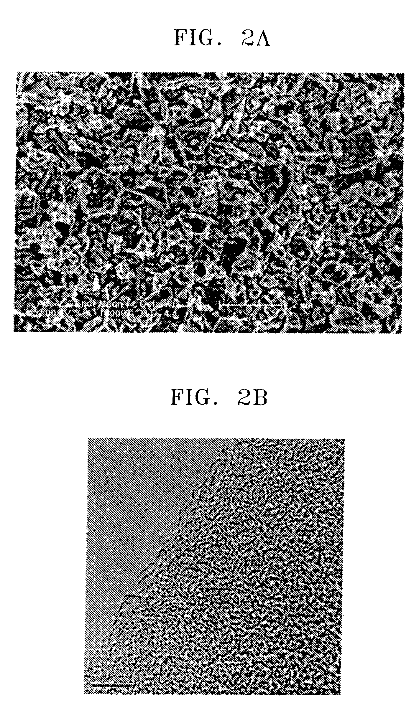
[0062]100 g of α-SiC having an average particle size of 0.7 mm as a carbon precursor was thermochemically reacted with Cl2 gas flowing at a flow rate of 3 l per minute at 1100° C. in a high-temperature electric furnace including a graphite reaction chamber and a transformer, so that Si was extracted from the carbon precursor. As a result, 30 g of a carbide-derived carbon material was prepared.

[0063]FIG. 2A is a SEM image and FIG. 2B is a TEM image of the carbide-derived carbon material prepared according to manufacturing example 1.

example 1

Preparation of Electron Emitter

(1) Preparation of Hybrid Composite Composition

[0064]0.5 g of the carbide-derived carbon material obtained according to Manufacturing Example 1, 1.0 g of carbon nanotubes, 37.5 g of poly(methyl methacrylate-co-methacrylic acid) copolymer (monomer ratio of 3:1, Mw of 12,000 g / mol), 26 g of trimethylolpropanethoxylatetriacrylate(TMPEOTA) acting as a crosslinking agent, 27.5 g of texanol acting as an organic solvent, 5 g of benzophenone acting as a photoinitiator, and 2.5 g of dioctylphthalate(DOP) acting as a plasticizer were mixed. The obtained mixture was uniformly mixed and dispersed using a 3-roll mill. As a result, a hybrid composite composition was prepared.

(2) Preparation of Electron Emitter

[0065]The hybrid composite composition was used as an ink and printed (using a commercially available piezo-type inkjet printer including a single nozzle) on a borosilicate glass substrate such that the printed hybrid composite composition coating layer had a w...

examples 2 through 5

Preparation of Electron Emitter

[0066]Hybrid composite compositions were prepared in the same manner as in Example 1, except that the amounts of the carbide-derived carbon material, carbon nanotubes, and vehicle according to Table 1 were used. The ratio of components of the vehicle was the same as in Example 1.

[0067]Electron emitters were prepared in the same manner as in Example 1, except that the hybrid composite compositions listed in Table 1 were used.

TABLE 1wt %Carbide-DerivedCarbon MaterialCarbon NanotubesVehicleExample 10.51.098.5Example 20.50.599Example 32197Example 440.0495.96Example 540.00495.996


PUM

PropertyMeasurementUnit
Timeaaaaaaaaaa
Poweraaaaaaaaaa
Nanoscale particle sizeaaaaaaaaaa

Abstract

Hybrid composites including carbon nanotubes and a carbide-derived carbon material, electron emitters including the hybrid composites, methods of preparing the electron emitters, and electron emission devices including the electron emitters are provided. Specifically, a hybrid composite includes at least one carbon nanotube and a carbide-derived carbon material. The carbide-derived carbon material is prepared by thermochemically reacting a carbide compound with a halogen-containing gas to extract substantially all of the elements except for the carbon in the carbide compound. Since the carbon nanotubes and the carbide-derived carbon material are hybridized and composited, a screen effect that may occur when large amounts of carbon nanotubes are used can be prevented, and an electron emitter including the hybrid composite has excellent electron emission capabilities, excellent uniformity, and a long lifetime.

Description

CROSS-REFERENCE TO RELATED PATENT APPLICATIONS[0001]This application claims priority to and the benefit of Korean Patent Application No. 10-2007-0045413, filed on May 10, 2007 in the Korean Intellectual Property Office, the entire content of which is incorporated herein by reference.BACKGROUND OF THE INVENTION[0002]1. Field of the Invention[0003]The present invention relates to hybrid composites including carbon nanotubes and carbide-derived carbon, electron emitters including the hybrid composites, methods of preparing the electron emitters, and electron emission devices including the electron emitters.[0004]2. Description of the Related Art[0005]In general, electron emission devices include electron emitters categorized into hot cathode type electron emitters and cold cathode type electron emitters. Examples of electron emission devices including cold cathode type electron emitters include field emitter array (FEA)-type electron emission devices, surface conduction emitter (SCE)-t...

Claims


Application Information

Patent Timeline
IPC IPC(8): H01B1/04B32B9/00B32B27/06B05D3/02
CPCB82Y10/00H01J1/304Y10T428/27H01J2329/00Y10S977/742H01J2201/30469B82Y40/00H01J9/025H01J2329/0455
Inventor KIM, YOON-JINKIM, JAE-MYUNGMOON, HEE-SUNGZANG, DONG-SIK
Owner SAMSUNG SDI CO LTD
Why Eureka
Try Eureka