Synchronization of sequential phase switchings in driving stator windings of a multiphase sensorless brushless motor at sub bemf-detectability speeds

a brushless motor and sequential phase technology, applied in the field of synchronization, can solve the problems of insufficient sensing precision, insufficient matching between distinct sense-fets, and hardly being detected

Active Publication Date: 2009-01-29
STMICROELECTRONICS SRL
View PDF2 Cites 21 Cited by
  • Summary
  • Abstract
  • Description
  • Claims
  • Application Information

AI Technical Summary

Benefits of technology

[0015]The method may have an intrinsic ability of extracting the useful voltage induced by transformer effect from other undesired components such as BEMF that may be present beyond no longer negligible rotor speeds by purposely choosing to double sample, during ON-phases and during OFF-phases of the drive signal, and compare the current sample with the previous sample (that has opposite sign), practically canceling any “common mode” BEMF component and use the result as the useful feedback signal.
[0016]In general, the method may make less critical and practically automatic handovers from the start-up mode to the BEMF-closed loop run mode and such a characteristic is also present when passing from the BEMF-closed loop run mode to a closed loop mo

Problems solved by technology

However, the amplitude of the BEMF is proportional to the speed of the rotor (BEMF=Ke*speed), thus it can hardly be detected if the rotor speed is too low, as at start up.
Typically, a sense resistor is used, but this may result in an added cost.
Other methods use current sensors integrated within the power devices (sense-FET) but sensing precision (matching among distinct sense-FETs) is often insufficient.
A general drawback of methods based on saturating the magnetic circuit is the relatively long time required for the measurements.
This latency causes a phase error (when the rotor is already moving) and limits the maximum

Method used


Image

  • Synchronization of sequential phase switchings in driving stator windings of a multiphase sensorless brushless motor at sub bemf-detectability speeds
  • Synchronization of sequential phase switchings in driving stator windings of a multiphase sensorless brushless motor at sub bemf-detectability speeds
  • Synchronization of sequential phase switchings in driving stator windings of a multiphase sensorless brushless motor at sub bemf-detectability speeds

Examples


first embodiment

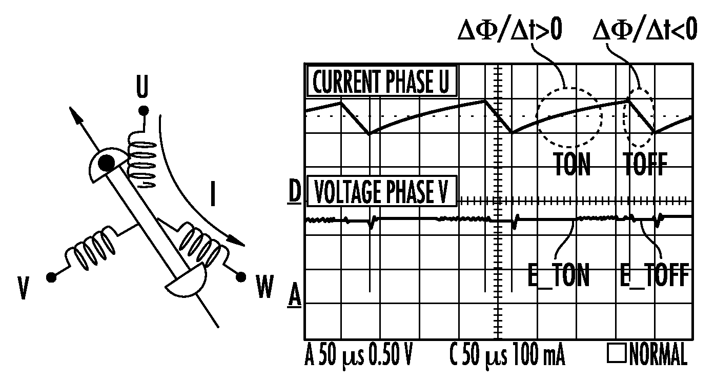
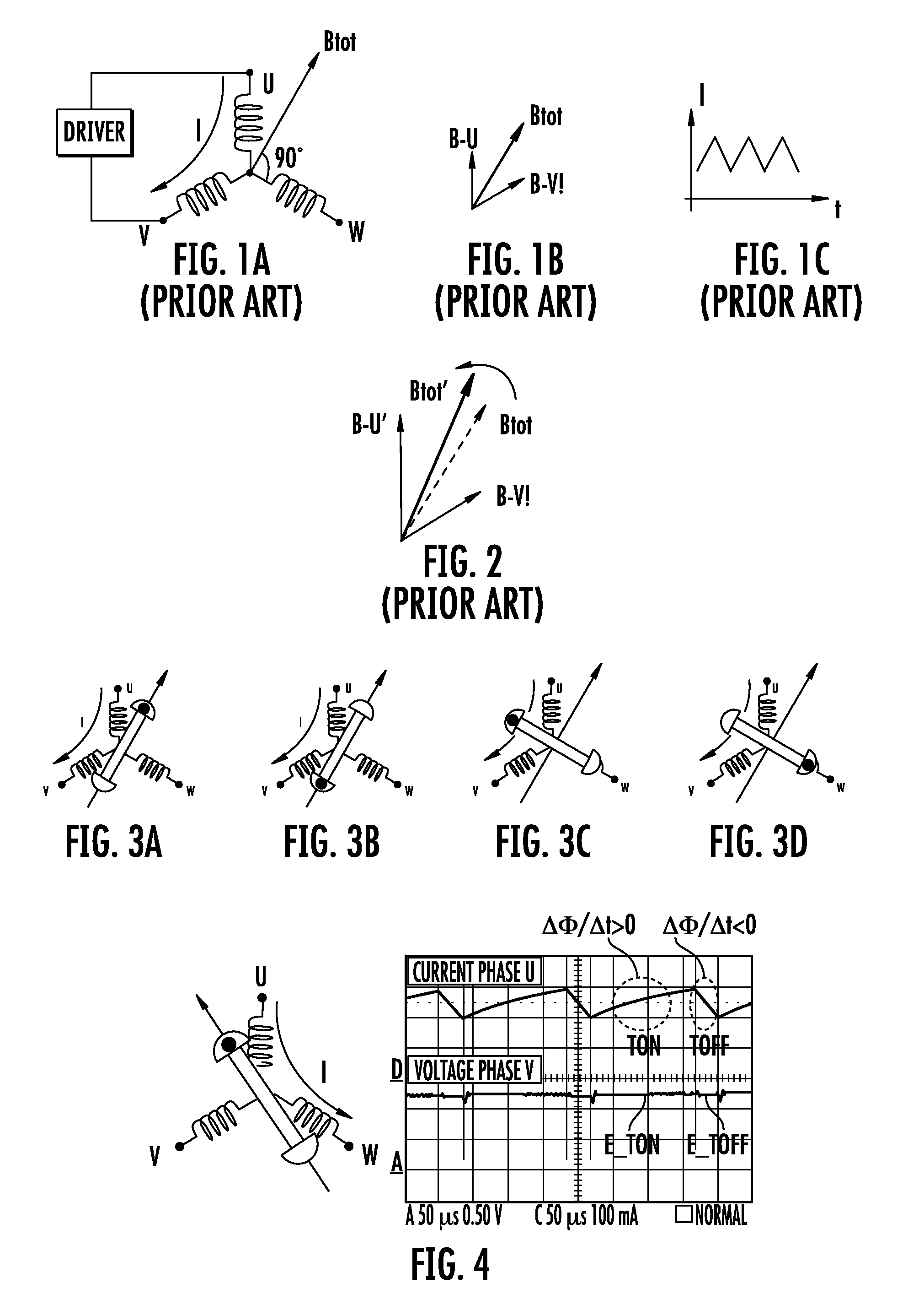
[0065]Two phase windings of a three phase stator (U and W for example) are commonly driven with a periodic control voltage (typically a PWM or PWM-like drive control signal) producing a current through the inductive windings having a significant ripple. The drive current ripple will generate induced voltages “E” (by transformer effect) on the floating third phase winding. The sign of the induced voltage “E” sampled during either the TON interval or during the TOFF interval of the PWM or PWM-like control signal provides an effective feedback signal for a startup procedure.

[0066]According to the method, it is sufficient to drive the phase windings according to a first phase windings configuration with a sequence of TON and TOFF phases of the drive signal as long as the sign of the voltage induced on the non-conductive phase winding assumes the expected value (Expected E) for the first implemented configuration and when this occurs excitation is switched to the next phase windings conf...

second embodiment

Enhanced Torque

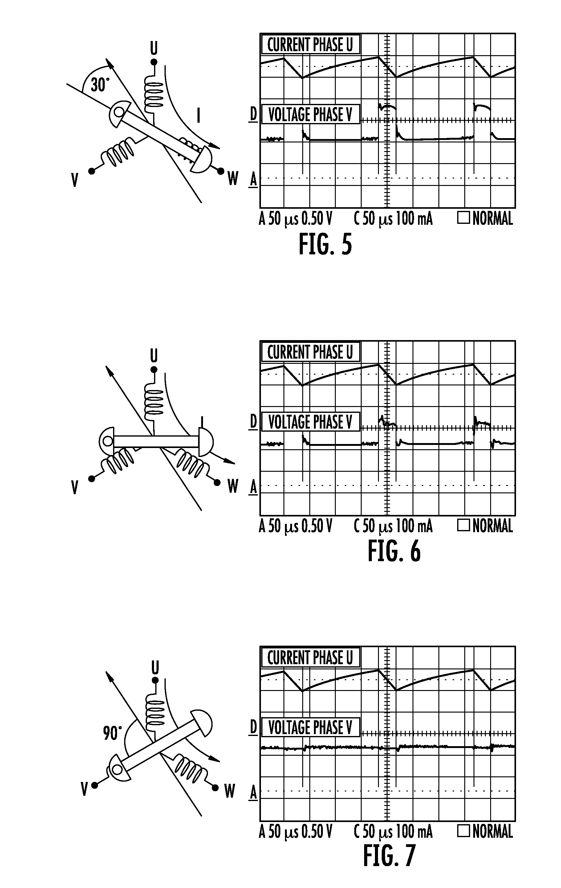
[0085]Different from the first embodiment, the driving of the currently selected phase windings according to a first configuration (Step1) is performed for a certain pre-established time Tstep1 instead of being continued as long as verifying an expected condition (E=Expected E) of inversion of the sign of the sampled enhanced voltage on the non-conductive winding. Each of the six phase driving configurations that are sequentially implemented upon detecting the expected sign of the sampled induced voltage, include a sub-sequence of cyclic phase switchings that continues until the expected sign of the sampled voltage for the particular phase is verified.

[0086]For each driving configuration, after a first interval of drive Tstep1 at least a successive configuration (Step2) of the cyclic drive sequence is excited for a pre-established time Tstep2 such to advance the angular orientation of the stator magnetic field vector by 60° degrees. For example, if the driven stator p...

third embodiment

Cancellation of any Superimposed BEMF

[0094]According to an intrinsic advantage of the method, the processing of the signal sensed at the tap of the phase winding that is non-conductive does not require any burdensome filtering as in the prior art systems, rather the method may simply compare samplings done both during TOFF and during TON phase of the drive signal for extracting the induced voltage unaffected by any BEMF. The effects of the BEMF that become of relevance at relatively high speed are substantially nullified making possible to detect the sign of the induced voltage “E” on the non-conductive phase winding by transformer effect even at high speeds. According to this embodiment, the induced voltage E is double sampled during TON and during TOFF phases of the drive signal and the two successive samples are compared. Of course, this requires the use of a “Sample&Hold” circuit. The manner of sampling during the TOFF phase must be chosen correctly depending on the method used ...


PUM


Abstract

The method of synchronizing sequential phase switchings in driving stator windings of a multiphase sensorless brushless motor with a reconstructed information on the current angular position of a permanent magnet rotor, includes sampling on a currently non-conductive stator winding a voltage induced thereon by the resultant magnetic field produced by the drive current forced through currently conductive stator windings that inverts its sign when the rotor transitions across a plurality of significant angular positions, at which orthogonality between the resultant magnetic field and a magnetic axis of the non-excited winding verifies. The sign of the sampled voltage induced on the currently non-excited winding is compared with the sign that is expected upon transiting across the angular position of inversion by the moving rotor for the current phase drive configuration to sequentially switch to the next phase drive configuration upon verifying conformity of the sign of the sampled voltage with the expected sign.

Description

FIELD OF THE INVENTION[0001]This invention relates to start-up and active braking to standstill techniques of brushless motors that do not use sensors of the angular position of the rotor. Motors of this type are largely used as spindle motors in Hard Disks, CDs, DVDs and the like.BACKGROUND OF THE INVENTION[0002]Sensorless brushless motors include a stator that most commonly includes three phase windings in a star configuration and a permanent magnet rotor. Through appropriate excitation sequences of the stator windings, a rotating magnetic field that causes attraction-repulsion forces on the permanent magnet of the rotor is produced. Such an electric machine is synchronous and to work correctly the stator rotating magnetic field should maintain a certain phase lag from the rotor magnetic field. For ensuring this condition it may be necessary to know at any instant the rotor angular position and to consequently drive the stator windings.[0003]In sensorless motors, the back electrom...

Claims


Application Information

Patent Timeline
IPC IPC(8): H02P6/18
CPCH02P6/182
Inventor BOSCOLO BERTO, MICHELE
Owner STMICROELECTRONICS SRL
Why Eureka
Try Eureka