Separator for fuel cell and method for manufacturing the same

Inactive Publication Date: 2009-02-12
HONDA MOTOR CO LTD
View PDF1 Cites 18 Cited by
  • Summary
  • Abstract
  • Description
  • Claims
  • Application Information

AI Technical Summary

Benefits of technology

[0043]In this process, the new passivation film also can be formed, for example, wherein the fuel cell separator is exposed to air or oxygen after performing acid washing, and before performing a subsequent step. However, it is preferable that heating be performed at a temperature of 200 to 280° C., so that when he

Problems solved by technology

Therefore, it is difficult to perform polishing after the wavy portion has been provided because, in this case, there is a concern that the wavy portion may become crushed, since both end surfaces of the wavy portion are interposed under pressure during polishing.
To avoid this i

Method used


Image

  • Separator for fuel cell and method for manufacturing the same
  • Separator for fuel cell and method for manufacturing the same
  • Separator for fuel cell and method for manufacturing the same

Examples


Embodiment Construction

[0054]A fuel cell separator according to the present invention, and a method for manufacturing the same, shall be explained in detail below with reference to the accompanying drawings, in which preferred embodiments of the present invention are presented. Constitutive components, which are the same as those shown in FIG. 10, are designated by the same reference numerals, and detailed explanations of such features shall be omitted.

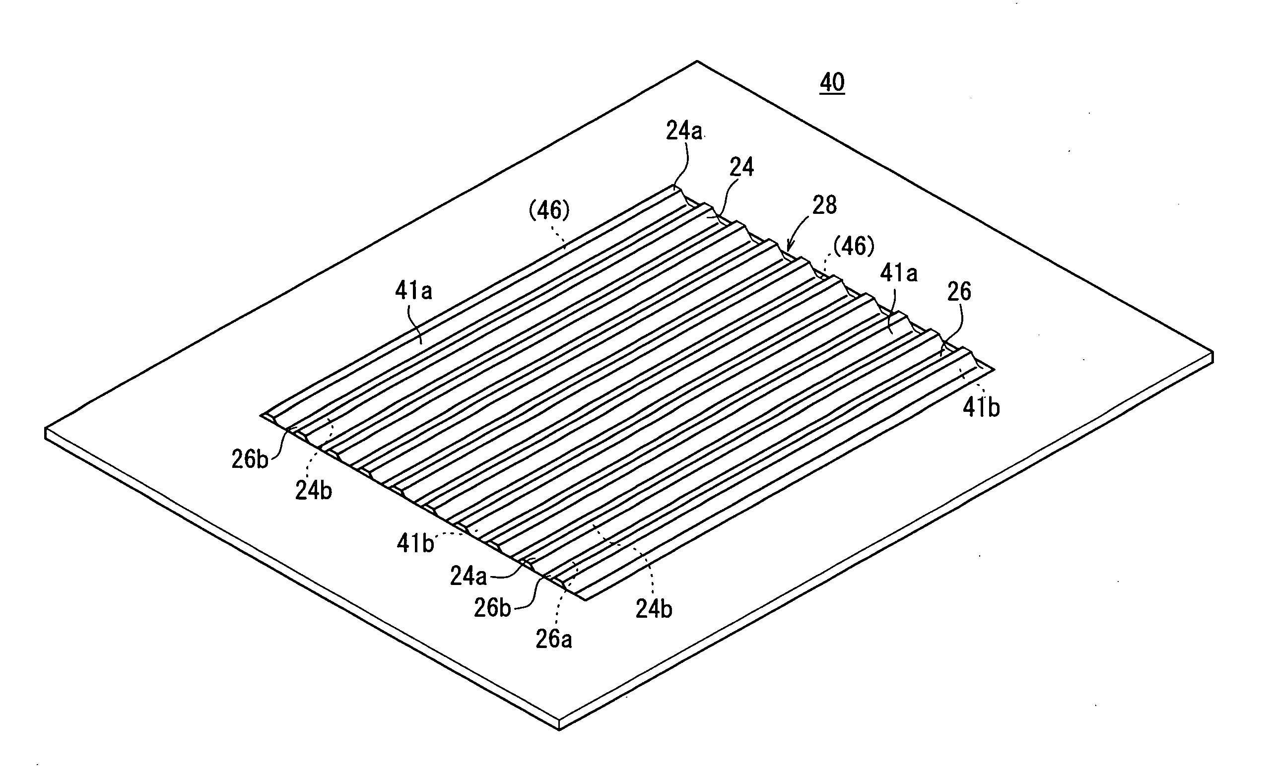
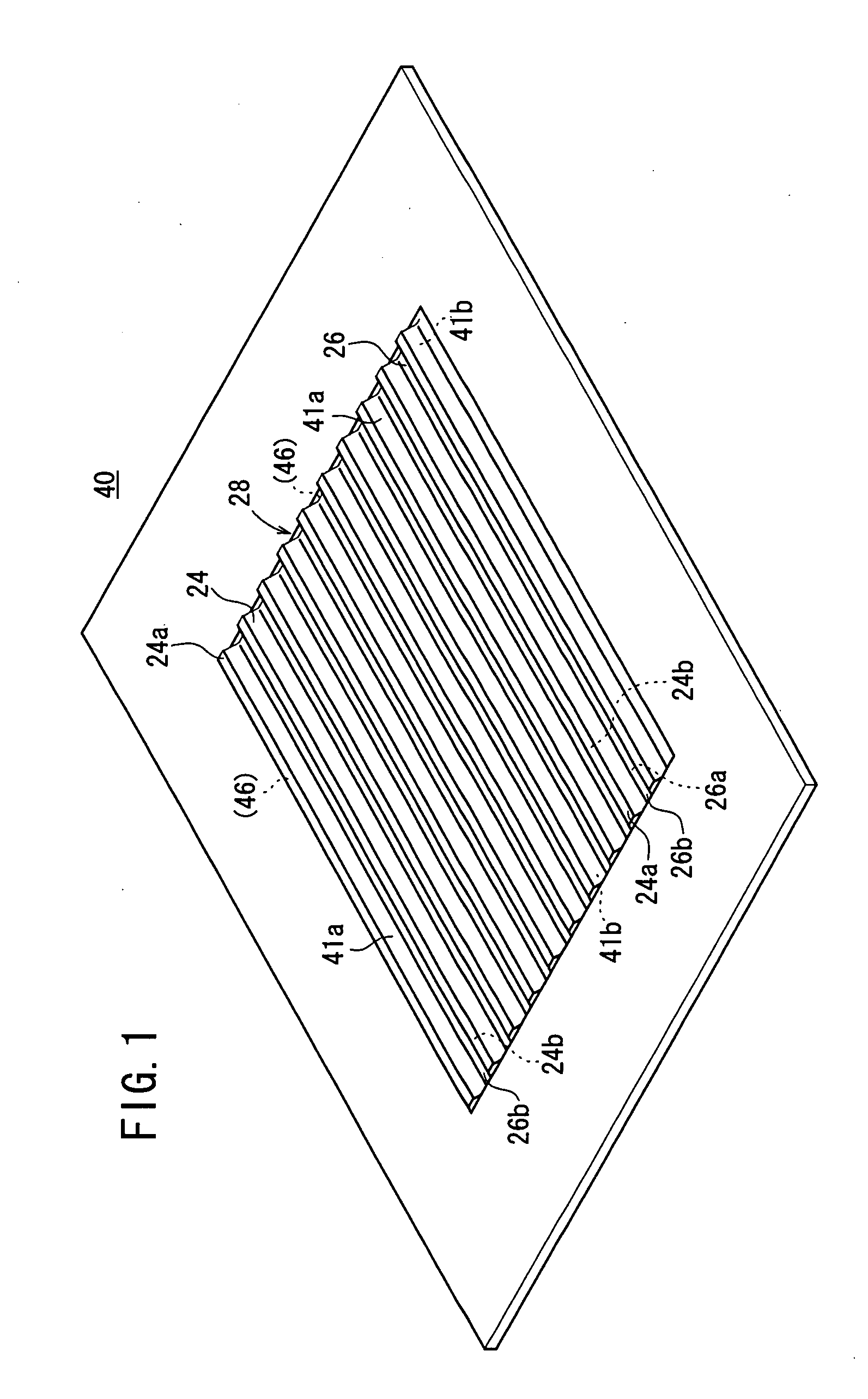
[0055]FIG. 1 is a schematic perspective view illustrating an entire fuel cell separator 40, according to an embodiment of the present invention. A wavy portion 28 is provided, for example, by means of a press forming process, on the fuel cell separator 40, which is composed of stainless steel.

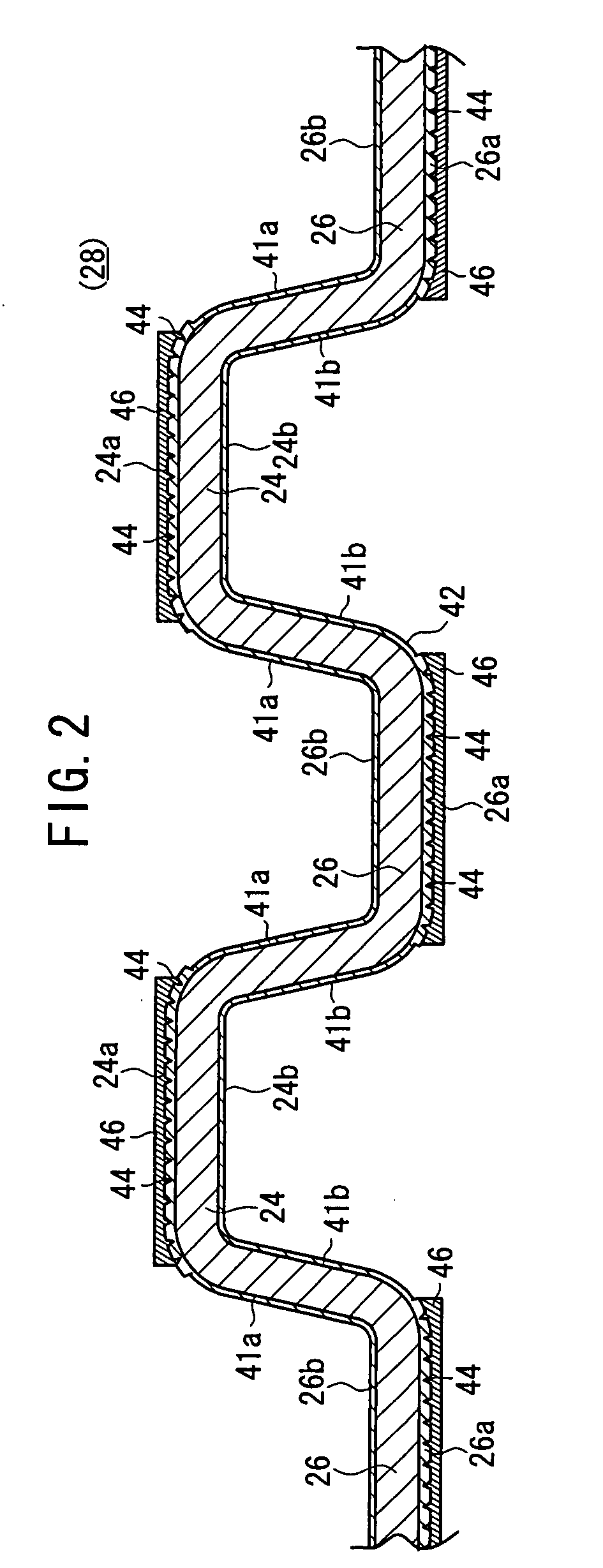
[0056]As shown in FIG. 2, the wavy portion 28 includes first protrusions 24, which protrude from one end surface of the fuel cell separator 40, together with second protrusions 26, which protrude in a direction opposite to the first protrusions 24, such that the first ...


PUM

PropertyMeasurementUnit
Temperatureaaaaaaaaaa
Thicknessaaaaaaaaaa
Angleaaaaaaaaaa

Abstract

At first step S1, a passivation film is removed by performing pickling on a separator for fuel cell and then a new passivation film is formed b performing heating at 200-280° preferably. At second step S2, mechanical polishing is performed on the horizontal top surfaces in the waiving portion of the separator for fuel cell, and a chipped portion is provided by chipping off a part of the passivation film. At third step S3, the separator for fuel cell is plated to form a first plating film composed of gold, rhodium, platinum or an alloy of two or more kinds of them starting at the periphery of the chipped portion. A complex ion stabilizer for suppressing dissociation of complex ions is added to plating bath.

Description

TECHNICAL FIELD[0001]The present invention relates to a separator for a fuel cell in which a plating coating film is selectively provided on horizontal top surfaces of protrusions that form a wavy portion, and a method for manufacturing the same.BACKGROUND ART[0002]In recent years, fuel cells have attracted attention as concerns increase concerning environmental protection, for the following reason. Specifically, only H2O is generated in the fuel cell, and atmospheric air is not polluted thereby.[0003]As shown in FIG. 10, a fuel cell 10 is constructed as a stack made up of a plurality of stacked unit cells 12. In the unit cell 12, an electrolyte-electrode assembly 20, in which an electrolyte or an ion exchange membrane 18 intervenes between an anode 14 and a cathode 16, is interposed between a pair of separators 22, 22 constituting the fuel cell. In general, for example, stainless steel or a titanium alloy is selected as the material for the fuel cell separators 22.[0004]Each of the...

Claims


Application Information

Patent Timeline
IPC IPC(8): H01M2/14C25D3/56C25D3/62C25D3/50C25D3/48
CPCC23C18/42C25D5/02C25D7/00H01M8/0206Y02E60/50H01M8/0228H01M8/0254H01M2008/1095H01M8/021Y02P70/50
Inventor KOBAYASHI, KOJIKITAFUJI, MASAHARUASAI, NOBUHIROKONDO, TETSUYAKAWAMATA, YUNAKAO, YASUHIRO
Owner HONDA MOTOR CO LTD
Why Eureka
Try Eureka