Motor drive circuit, method, and cooling device using the same

a technology of motor drive and cooling device, which is applied in the direction of motor/generator/converter stopper, electronic commutator, dynamo-electric converter control, etc., can solve the duty ratio of pulse-width modulated signal, large heat generated, and heat from an lsi leading to thermorunaway in the lsi itself. achieve the effect of improving the degree of freedom of rotation control

Active Publication Date: 2009-02-19
ROHM CO LTD
View PDF1 Cites 35 Cited by
  • Summary
  • Abstract
  • Description
  • Claims
  • Application Information

AI Technical Summary

Benefits of technology

[0041]According to this embodiment, by combining the three voltages, which are the first and the second control voltages, and the rotation control voltage, it is possible to set duty ratios of various pulse-modulated drive signals in various ways, and it is possible to improve degrees of freedom of rotation control when the motor is started up. Furthermore, in the present specification, “amplification” includes attenuation with gain of less than 1, and

Problems solved by technology

In such LSIs, as the operating speeds, that is, clock frequencies, become higher, amounts of heat generated become large.
There is a problem in that the generated heat from an LSI leads to thermorunaway in the LSI itself, or impacts on neighboring circuits.
Furthermore, Patent Document 3 discloses technology in which a duty ratio of a pulse-width modulated signal is limited, so that a fan motor rotates at or above a predetermined minimum number of rotations.
Therefore, as described above, when the coil current rapidly increases, a very large back electromotive voltage occurs, and there is a risk of the rating of the drive circuit being exceeded.
1. There has been a problem in that, when a rotating motor is stopped, a regenerative current flows in a coi

Method used


Image

  • Motor drive circuit, method, and cooling device using the same
  • Motor drive circuit, method, and cooling device using the same
  • Motor drive circuit, method, and cooling device using the same

Examples


first embodiment

[0069]Several embodiments of the present invention relate to a motor drive circuit used in a cooling device for cooling electronic computers, such as desktop or laptop personal computers, workstations, or the like, or electronic devices, such as refrigerators or the like.

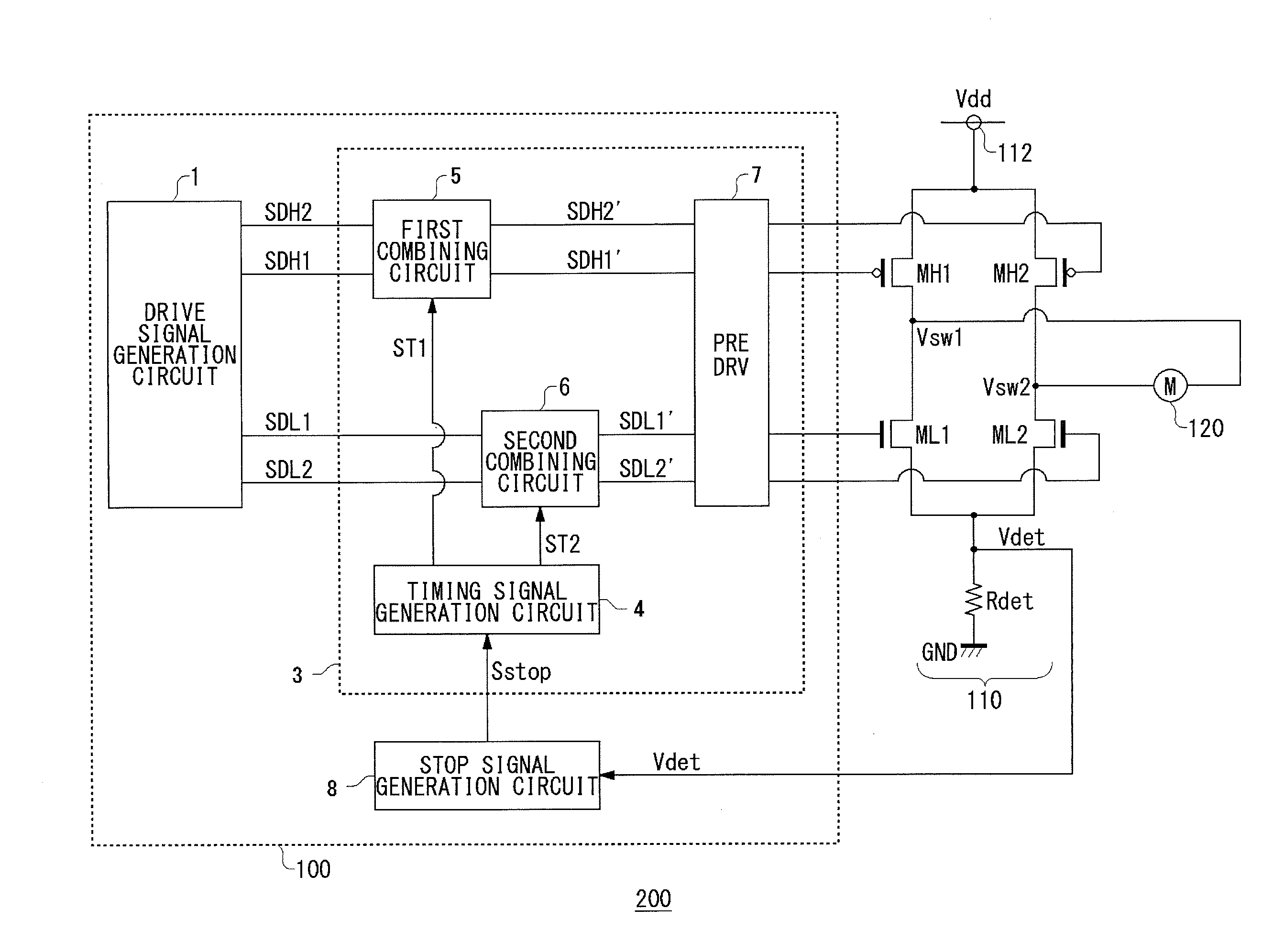
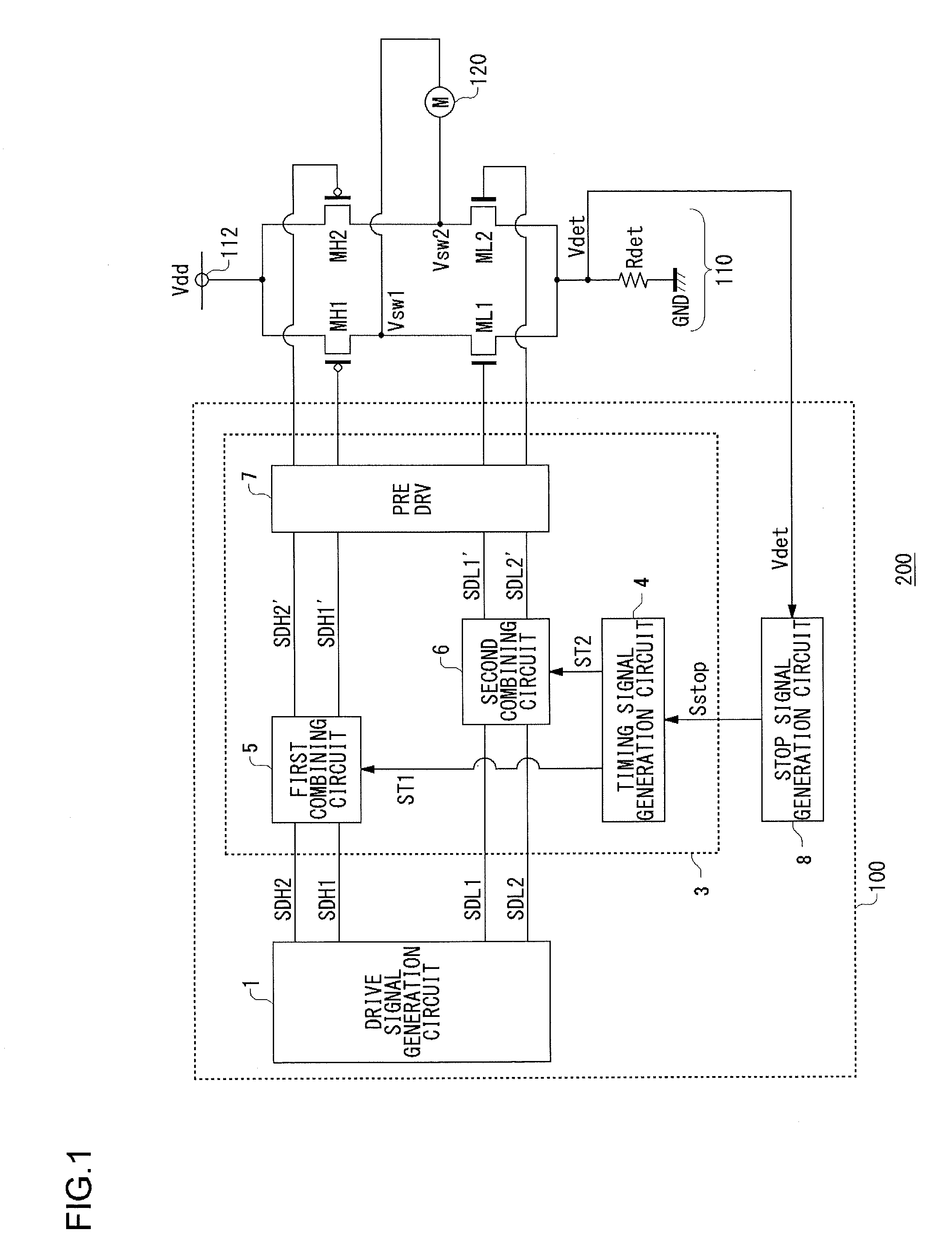
[0070]FIG. 1 is a circuit diagram showing a configuration of a cooling device 200 according to a first embodiment of the present invention. The cooling device 200 includes a motor drive circuit 100, a H-bridge circuit 110, and a fan motor 120.

[0071]The fan motor 120 is a single-phase full-wave motor in the present embodiment, and is arranged facing an object to be cooled, which is not shown in the figure. In the fan motor 120, a coil current, that is, a conduction state, is controlled to control rotation, by switching signals Vsw1 and Vsw2 generated by the motor drive circuit 100 and the H-bridge circuit 110.

[0072]The H-bridge circuit 110 includes a first high side transistor MH1, a second high side transistor MH2, ...

second embodiment

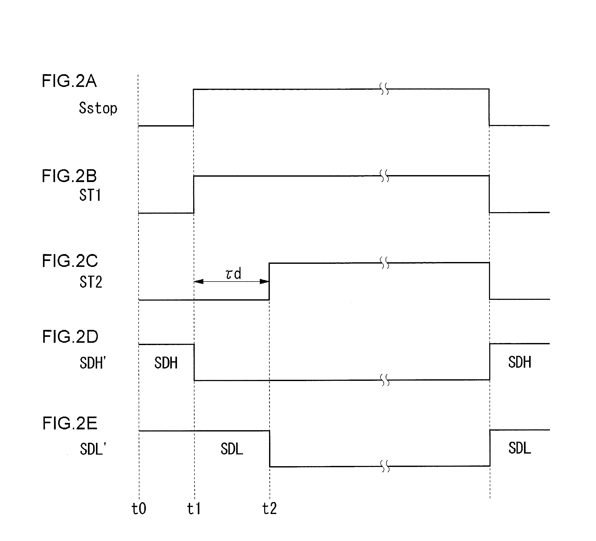
[0107]In the first embodiment, in a time period from when the stop signal Sstop goes to a high level, to when the delay time τd elapses, ON and OFF states of the low side transistors (the high side transistors in the modified example) are set based on drive signals outputted from the drive signal generation circuit 1. Compared with this, in the second embodiment, in a time period from when a stop signal Sstop goes to a high level, to when a delay time τd elapses, the two low side transistors are forcibly turned ON and OFF.

[0108]A motor drive circuit 100 according to the second embodiment may be basically configured similarly to FIG. 1. For example, by inputting the first timing signal ST1, in addition to a second timing signal ST2, to a second combining circuit 6, and performing a logical operation on the two timing signals, a time period in which the first timing signal ST1 only has a high level is detected. In a time period in which the first timing signal ST1 only has a high leve...

third embodiment

[0121]An embodiment of the present invention relates to a motor drive circuit used in a cooling device for cooling electronic computers such as desktop or laptop personal computers, workstations, or the like, or electronic devices such as refrigerators or the like.

[0122]FIG. 7 is a circuit diagram showing a configuration of a cooling device 200 according to a third embodiment of the present invention. The cooling device 200 includes a motor drive circuit 100a, a H-bridge circuit 110, and a fan motor 120.

[0123]The fan motor 120 is a single-phase full-wave motor in the present embodiment, and is arranged facing an object to be cooled, which is not shown in the figure. In the fan motor 120, a coil current, that is, a conduction state, is controlled, to control rotation by switching signals Vsw1 and Vsw2 generated by the motor drive circuit 100a and the H-bridge circuit 110.

[0124]The H-bridge circuit 110 includes a first high side transistor MH1, a second high side transistor MH2, a fir...


PUM


Abstract

A drive signal generation circuit generates drive signals that control ON and OFF states of transistors of a H-bridge circuit, in accordance with a target value of torque. A driver circuit alternatively turns ON and OFF high side transistors, and low side transistors of the H-bridge circuit, based on the drive signals outputted from the drive signal generation circuit. The driver circuit immediately turns OFF the high side transistors, when an instruction is issued to stop a motor, and after a predetermined delay time τd has elapsed, turns OFF the low side transistors.

Description

BACKGROUND OF THE INVENTION[0001]1. Field of the Invention[0002]The present invention relates to motor drive technology.[0003]2. Description of the Related Art[0004]1. In recent years, with the speeding up of personal computers and workstations, operating speeds of LSIs (Large Scale Integrated circuits) for processing in CPUs (Central Processor Units), DSPs (Digital Signal Processors), and the like, have been increasing.[0005]In such LSIs, as the operating speeds, that is, clock frequencies, become higher, amounts of heat generated become large. There is a problem in that the generated heat from an LSI leads to thermorunaway in the LSI itself, or impacts on neighboring circuits. Therefore, appropriate heat cooling of the LSIs has become a very important technology.[0006]As an example of technology for cooling the LSI, there is a cooling method comprising an air-cooling system by a cooling fan. In this method, for example, the cooling fan is installed facing a surface of the LSI, and...

Claims


Application Information

Patent Timeline
IPC IPC(8): H02P3/12H02P7/29
CPCH02P7/29H02P7/28
Inventor HAYASHI, HIROAKISATAKE, TOSHIKAZU
Owner ROHM CO LTD
Why Eureka
Try Eureka