
Chloride-free thermal batteries using molten nitrate electrolytes

a technology of molten nitrate and thermal batteries, which is applied in the direction of molten electrolytes, cell components, electrochemical generators, etc., can solve the problems of rapid destruction of metal oxide based cathode materials, use of modern high-voltage metal oxide cathode materials, and shorten the activation time of thermal batteries. , the effect of reducing the weight of heat sources

Active Publication Date: 2009-02-19
AXIENT LLC
View PDF16 Cites 14 Cited by
  • Summary
  • Abstract
  • Description
  • Claims
  • Application Information

AI Technical Summary

Benefits of technology

[0011]Another object of the invention is the use of nitrate salts as a lower melting electrolyte, which shortens a thermal battery cell's activation time and reduces the weight of heat sources and insulation.
[0012]It is another object of the invention that the nitrate also functions as the cathode material or oxidizer, thus simplifying battery construction by eliminating the necessity for the addition of a separate oxidizer.

Problems solved by technology

Because of its strictly military applications, thermal battery technology has evolved much slower than commercial battery technology.
Furthermore, the use of LiCl—KCl and related halide electrolytes prevents the use of modern high-voltage metal oxide cathode materials such as V2O5, LiCoO2, and LiMn2O4.
The aggressive attack by chloride ions at high temperatures results in the rapid destructions of metal oxide based cathode materials.
In addition, the much lower operating temperatures offer longer operating lifetimes for molten nitrate electrolyte-based thermal batteries.
The major problem that must be solved before molten nitrate based thermal batteries become practical is the minimization of unwanted gas-production reactions within the battery.

Method used


Image

  • Chloride-free thermal batteries using molten nitrate electrolytes

Examples


Embodiment Construction

[0018]The invention summarized above and defined by the enumerated claims may be better understood by referring to the following description, which should be read in conjunction with the accompanying drawing. This description of an embodiment, set out below to enable one to build and use an implementation of the invention, is not intended to limit the enumerated claims, but to serve as a particular example thereof. Those skilled in the art should appreciate that they may readily use the conception and specific embodiments disclosed as a basis for modifying or designing other methods and systems for carrying out the same purposes of the present invention. Those skilled in the art should also realize that such equivalent assemblies do not depart from the spirit and scope of the invention in its broadest form.

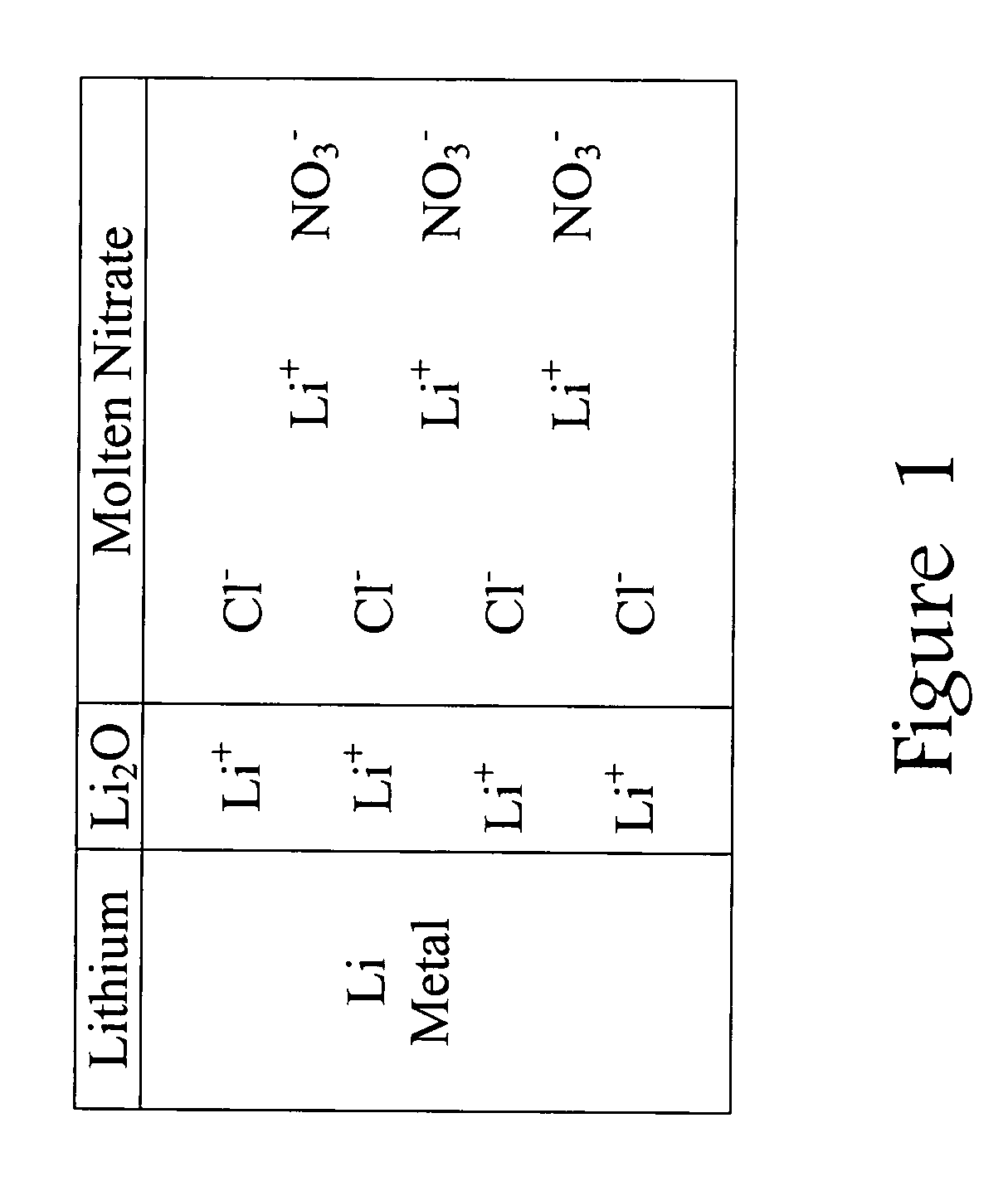
[0019]This invention is based on a model that explains how chloride ions (Cl−) in the molten nitrate electrolyte can lead to gas-producing reactions involving the lithium-based an...


PUM


Abstract

Thermal batteries using molten nitrate electrolytes offer significantly higher cell voltages and marked improvements in energy and power densities over present thermal batteries. However, a major problem is gas-evolution reactions involving the molten nitrate electrolytes. This gassing problem has blocked the advantages offered by thermal batteries using molten nitrates. The solution to this problem is the use of chloride-free molten nitrate electrolytes. Most important is the avoidance of potassium perchlorate (KClO4) or any other chlorine-containing substances that can decompose to produce chloride ions in any thermal battery component. The Fe+KClO4 pyrotechnic used to activate thermal batteries is a key example. The decomposition of such substances into chloride ions (Cl−) results in passivating-film breakdown and gas-producing reactions with the molten nitrate electrolyte. These reactions largely involve the lithium-component of the anode used in thermal batteries such as Li—Fe (LAN), Li—Si, and Li—Al. The introduction of chloride ions into the nitrate melt via the pyrotechnic materials produces a rapid breakdown of the protective oxide film on lithium-based anodes and leads to gas-producing reactions.

Description

BACKGROUND OF THE INVENTION[0001]1. Field of the Invention[0002]The present invention pertains to thermally activated electrochemical cells, and more particularly relates to thermal battery cells and still more particularly to thermally activated battery cells including a novel electrolyte system that is chloride free.[0003]2. Background of the Prior Art[0004]Thermal batteries are used in all types of military devices that require long shelf lives (up to 20 years), and rapid activation (less than one second), and high energy and power densities. Prime application examples are air-to-air missiles such as the Sidewinder missile. Modern technology is placing increasing heavy requirements for electrical power in many weapon applications, thus thermal batteries with higher cell voltages and higher energy and power densities are presently in demand. Because of its strictly military applications, thermal battery technology has evolved much slower than commercial battery technology. Thermal...

Claims


Application Information

Patent Timeline
IPC IPC(8): H01M6/36
CPCH01M4/40H01M4/505H01M4/525H01M6/36Y02E60/528H01M14/00H01M2300/0062Y02E60/122H01M8/182Y02E60/50
Inventor MILES, MELVIN H.
Owner AXIENT LLC
Learn More