Method for Radiation Tolerance by Automated Placement

a technology of automatic placement and radiation tolerance, applied in the direction of instruments, computing, electric digital data processing, etc., can solve the problems of large number of cells, difficult physical design without the aid of computers, and complicated connections between cells

a technology of automatic placement and radiation tolerance, applied in the direction of instruments, computing, electric digital data processing, etc., can solve the problems of large number of cells, difficult physical design without the aid of computers, and complicated connections between cells

US20090049418A1Inactive Publication Date: 2009-02-19GLOBALFOUNDRIES INC

Image

  • Method for Radiation Tolerance by Automated Placement
  • Method for Radiation Tolerance by Automated Placement
  • Method for Radiation Tolerance by Automated Placement

Examples


Embodiment Construction

)

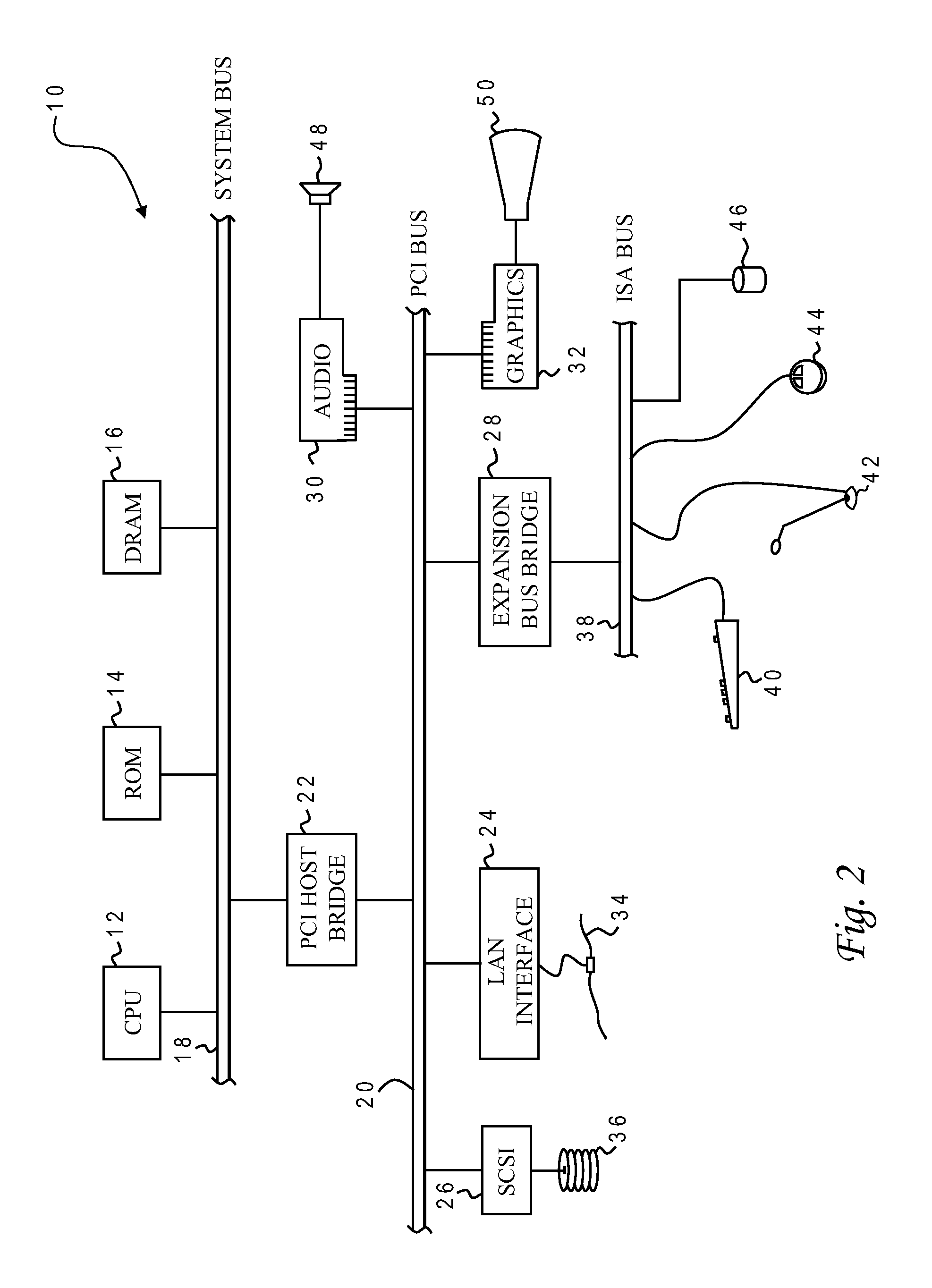
[0024]With reference now to the figures, and in particular with reference to FIG. 2, there is depicted one embodiment 10 of a computer system programmed to carry out computer-aided design of an integrated circuit in accordance with one implementation of the present invention. System 10 includes a central processing unit (CPU) 12 which carries out program instructions, firmware or read-only memory (ROM) 14 which stores the system's basic input / output logic, and a dynamic random access memory (DRAM) 16 which temporarily stores program instructions and operand data used by CPU 12. CPU 12, ROM 14 and DRAM 16 are all connected to a system bus 18. There may be additional structures in the memory hierarchy which are not depicted, such as on-board (L1) and second-level (L2) caches. In high performance implementations, system 10 may include multiple CPUs and a distributed system memory.

[0025]CPU 12, ROM 14 and DRAM 16 are also coupled to a peripheral component interconnect (PCI) local bus 2...


PUM


Abstract

A method of designing a layout of an integrated circuit for increased radiation tolerance by ensuring that any critical components (those deemed particularly sensitive to radiation-induced soft errors) are at spacings greater than a predetermined threshold based on particle migration within the silicon substrate. The method starts with an initial placement, identifies the objects for which radiation tolerance is desired, determines whether any of those objects and, if so, moves the relevant objects to increase the spacing. An exemplary threshold for contemporary CMOS device technologies is 5 μm. The objects can be moved by vertically and / or horizontally shifting away from a reference point of the integrated circuit. The critical objects may include triplicated (redundant) structures, clock control latches, or a reset bit. The method can be used in conjunction with other placement optimizations such as area, power and timing.

Description

BACKGROUND OF THE INVENTION[0001]1. Field of the Invention[0002]The present invention generally relates to the fabrication and design of semiconductor chips and integrated circuits, and more particularly to a method of designing the physical layout (placement) of latches and other logic cells to improve radiation tolerance.[0003]2. Description of the Related Art[0004]Integrated circuits are used for a wide variety of electronic applications, from simple devices such as wristwatches to the most complex computer systems. A microelectronic integrated circuit (IC) chip can generally be thought of as a collection of logic cells with electrical interconnections between the cells, formed on a semiconductor substrate (e.g., silicon). An IC may include a very large number of cells and require complicated connections between the cells. A cell is a group of one or more circuit elements such as transistors, capacitors, resistors, inductors, and other basic circuit elements grouped to perform a ...

Claims


Application Information

Patent Timeline
19 Feb 2009
Publication
US20090049418A1
IPC
G06F17/50
CPC
G06F17/5072; G06F30/392
Inventors
KLEINOSOWSKI, AJ; WILLENBORG, SCOTT M.