Dispensing system with material spill prevention system

a technology of material spill prevention and dispensing system, which is applied in the direction of liquid materials, packaging goods, transportation and packaging, etc., can solve the problems of increasing the level of foam spill, problematic foam-up, and high cost for users, and achieve the effect of improving position monitoring

Active Publication Date: 2009-03-05
PREGIS INTELLIPACK CORP
View PDF27 Cites 12 Cited by
  • Summary
  • Abstract
  • Description
  • Claims
  • Application Information

AI Technical Summary

Benefits of technology

[0046]An absolute position encoder that provides a resolution of better than one degree (when dealing with a rotary encoder) is preferred so that the system control processor knows relatively accurately where the valving rod is at all times. Thus, relative to the above noted PCT publication having a home sensor, the use of an absolute encoder avoids a need to count pulses away from a home position (although in a preferred embodiment the home positioner can be retained as a supplement to the absolute encoder with the latter providing improved position monitoring on an absolute time basis and can be added in a retrofit provided the control board has sufficient input/output capability to handle both signal feeds). In other words, in a monitoring system usi

Problems solved by technology

The cushioning quality bag can conform to a product in a package when placed in the package adjacent the product and allowed to expand (or vice versa with the product placed on a yet to fully expand bag) and avoid direct product contact with the product, which can be undesirable, particularly with dispensed material that has an adhesive quality as in polyurethane foam.
Unfortunately, it is quite common for the film being fed to the nip roller or other driver to halt or jam along its path of travel during the film feed process.
Accordingly, even though no bag is sufficiently formed to receive the output of the dispenser, the dispenser continues to output foam for each scheduled bag despite their non-presence, thus aggravating the level of foam spill.
Foam also tends to drop onto the floor under and around the machine.
Such “foam-ups” are problematic and costly to a user.
a) Significant production downtime for the customer;
b) Time-consuming service calls involving field representatives;
c) Replacement or refurbishment of foam coated internal mechanisms;
d) Hidden, subtle or latent damage to sensitive mechanical components, wiring, or electrical connectors;
e) Permanent cosmetic damage to the painted or plated surfaces and finely machined components of the dispensing system;
f) Foam damage to the operators facility, usually to the floor, or to the products that the operator is attempting to package;
g) Foam damage to the operators clothing and/or shoes;
h) Loss of operator confidence in the foam-in-bag dispensing system.
Unfortunately, it is also quite common, for an operator to run both webs of film together along, for example, the front face of the dispenser module wherein both webs of the C-fold film (or other film type as in double individual layer on single roll film types) are positioned to a common side of the dispenser module.
In so doing, the operator also may easily fail to see that both webs are not around the dispenser module properly.
This failure is particularly common when both webs are fed to the front of the dispenser, because the v

Method used


Image

  • Dispensing system with material spill prevention system
  • Dispensing system with material spill prevention system
  • Dispensing system with material spill prevention system

Examples


first embodiment

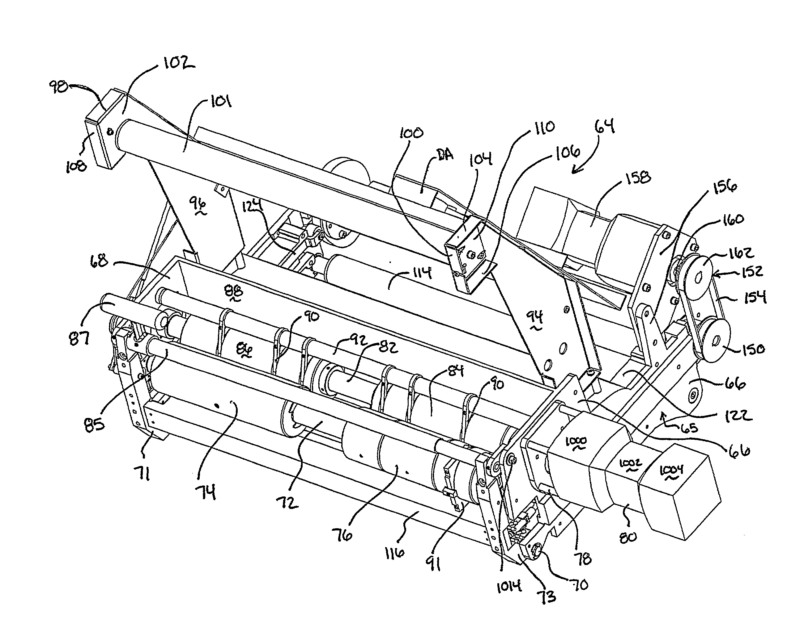
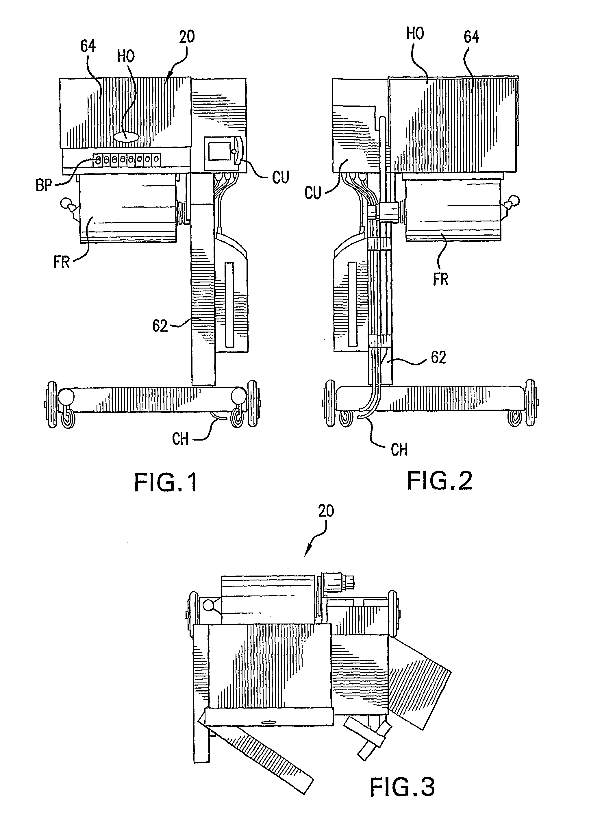
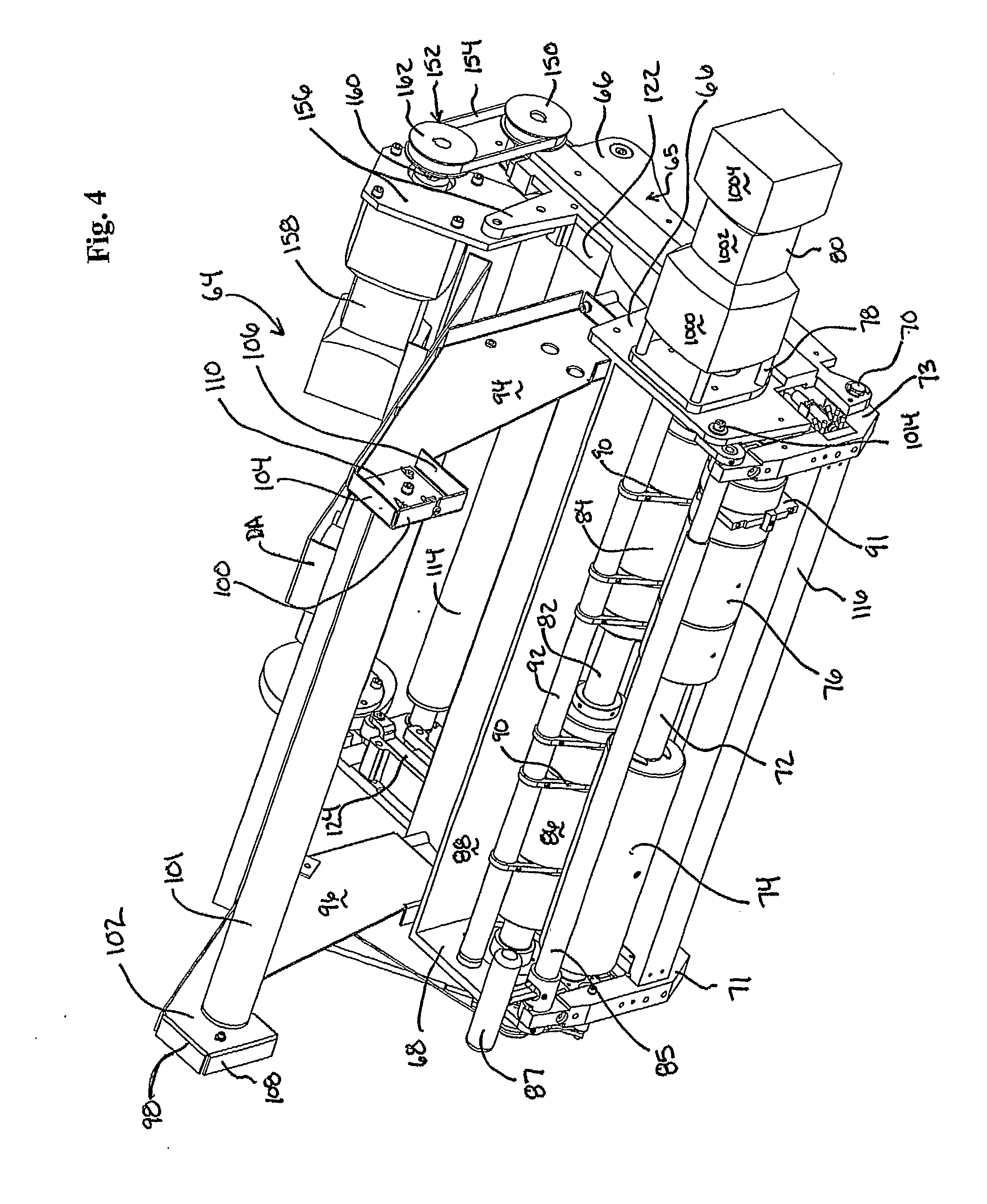
[0122]FIGS. 7 and 18 to 22 illustrate material spill avoiding dispensing system 1000 shown as comprising foam-in-bag dispensing system 20 with FIB assembly 64 and material spill prevention system 3000. Spill prevention system 3000 is particularly useful in systems such as the above described “FIB” dispensing system where there might be a highly disruptive foam-up situation (since typical foams are fast adhering, difficult to remove once set, and, due to their expansion, expand throughout the various nooks and crannies of the system), although any spill of material whether adhering or not is undesirable. In a preferred embodiment, wherein material spill prevention system 3000 is used in conjunction with a foam-in-bag dispensing system 20 to provide material spill avoiding dispensing system 1000 (only partially shown in FIGS. 7, 18 and 19), spill prevention system 3000 preferably comprises one or more sensors as in the left and right sensors 3100 and 3102 shown in FIGS. 18-21. Sensors...

second embodiment

[0156]the present invention features material spill prevention system 3000A (FIG. 26). To better appreciate features of material spill prevention system 300A reference is made to FIGS. 14 and 25 wherein there can be seen properly fed film webs WF, WR to opposite sides of the dispenser assembly 192 (as shown in FIG. 14) versus an improperly fed film web set wherein, as shown in FIG. 25, both webs WF, WR are fed to only one side of the dispenser (typically the misplacement is at the front of dispenser assembly 192 as there cannot be readily seen (particularly when opaque or darker web film is utilized) the relationship of the rear web relative to the dispenser housing).

[0157]FIG. 25 also illustrates the problematic release of foam precursor FP to regions external to a non-formed bag due to the film web misplacement and into the other components of the foam-in-bag (“FIB”) dispensing system 20 as in the film driving and electrical components for seal formation and sensing means for sens...


PUM

PropertyMeasurementUnit
Distanceaaaaaaaaaa

Abstract

A material spill prevention system with feed location sensing system to reduce the possibility of material spillage relative to the film being utilized for bag formation. The material spill prevention system monitors whether there is a proper film feed situation and, if not, precludes the release of material from the dispenser as in by precluding a flow controller opening and the release of material to the bag intended to receive the release chemical (e.g., a foam packaging bag). The prevention system is applicable to a variety of film feed arrangements as in a C-fold film drawn by a nip roller arrangement from a roll source with the dispenser mechanism positioned intermediate the nip and film source relative to film travel. An embodiment of the spill prevention system also features an absolute position transducer for monitoring position of a flow controller which controls output of material from the dispenser.

Description

FIELD OF THE INVENTION[0001]The present invention is directed at a material spill prevention system, a method of using a material spill prevention system and, in one embodiment, a material spill avoiding dispensing system such as one with a material-in-bag dispensing system combined with a material spill prevention system or one with a handheld dispenser system. A preferred embodiment of the invention includes a foam up prevention system for a foam-in-bag dispensing system as in a sensing system which detects when a film material used in bag formation is not in the proper position so as to avoid extensive foam spillage and / or a foam up prevention system that includes a position monitoring system of a device associated with the dispenser's flow or no-flow status.BACKGROUND OF THE INVENTION[0002]Many dispensing systems are known in the art and are used in different industries. These include foam dispensing systems that are used to dispense two component polyurethane foams in various a...

Claims


Application Information

Patent Timeline
IPC IPC(8): B65B1/30
CPCB29C44/60B29C44/182
Inventor BERTRAM, GEORGEWALKER, DOUGLAS
Owner PREGIS INTELLIPACK CORP
Why Eureka
Try Eureka