Sludge thickening device and sludge thickening method

a technology of sludge thickening and sludge, which is applied in the direction of separation process, instruments, filtration separation, etc., can solve the problems of clogging of cylinder screen, low thickening efficiency, suspended filtration liquid, etc., and achieves high screen surface recovery effect

Active Publication Date: 2009-03-05
ISHIGAKI CO LTD
View PDF11 Cites 19 Cited by
  • Summary
  • Abstract
  • Description
  • Claims
  • Application Information

AI Technical Summary

Benefits of technology

[0006]A first problem is that, for sludge having favorable filtration characteristics with low viscosity, a conventional screw press prevents occurrence of an excessive load and obtains a cake having a uniform moisture content by controlling the rotational speed of a screw and, however, for sludge having poor filtration characteristics, when the volume of a filtration chamber is decreased for compressing and dehydrating the sludge, a filtration surface of an outer cylinder screen is clogged at an early stage; or, when rapidly compressing the sludge, it is leaked from the outer cylinder screen along with filtration liquid, thus, there is a possibility that the filtration liquid is suspended. Thus, there is a problem that thickening efficiency is low, and it is difficult to cause the concentration of obtained thickened sludge to be uniform.

Problems solved by technology

A first problem is that, for sludge having favorable filtration characteristics with low viscosity, a conventional screw press prevents occurrence of an excessive load and obtains a cake having a uniform moisture content by controlling the rotational speed of a screw and, however, for sludge having poor filtration characteristics, when the volume of a filtration chamber is decreased for compressing and dehydrating the sludge, a filtration surface of an outer cylinder screen is clogged at an early stage; or, when rapidly compressing the sludge, it is leaked from the outer cylinder screen along with filtration liquid, thus, there is a possibility that the filtration liquid is suspended.
Thus, there is a problem that thickening efficiency is low, and it is difficult to cause the concentration of obtained thickened sludge to be uniform.
In addition, there is a problem that, for an apparatus which detects a concentration and a feed amount of raw slurry and control the concentration of thickened sludge and a torque, since an amount of supplied sludge and a concentration thereof are constantly changed and then running torques applied to a screw and an outer cylinder screen are changed, it is difficult to cause the concentration of the thickened sludge to be uniform.
A second problem is that, in a conventional differential rate rotary thickener, since a thickening efficiency changes depending on the ratio of the outer diameter of a screw shaft and the inner diameter of an outer cylinder screen, a high thickening efficiency is not necessarily achieved.
In addition, there is a problem that, in a conventional differential rate rotary thickener, a single screw vane does not necessarily contribute to achieving a high thickening efficiency with respect to various attributes of raw slurries of sludge to be thickened, a target concentration of thickened sludge, and the like.

Method used


Image

  • Sludge thickening device and sludge thickening method
  • Sludge thickening device and sludge thickening method
  • Sludge thickening device and sludge thickening method

Examples


first embodiment

[0062]A sludge thickener and a sludge thickening method of a first embodiment of the present invention are described in detail with reference to drawings.

[0063][1. A Sludge Thickener]

[Entire Constitution]

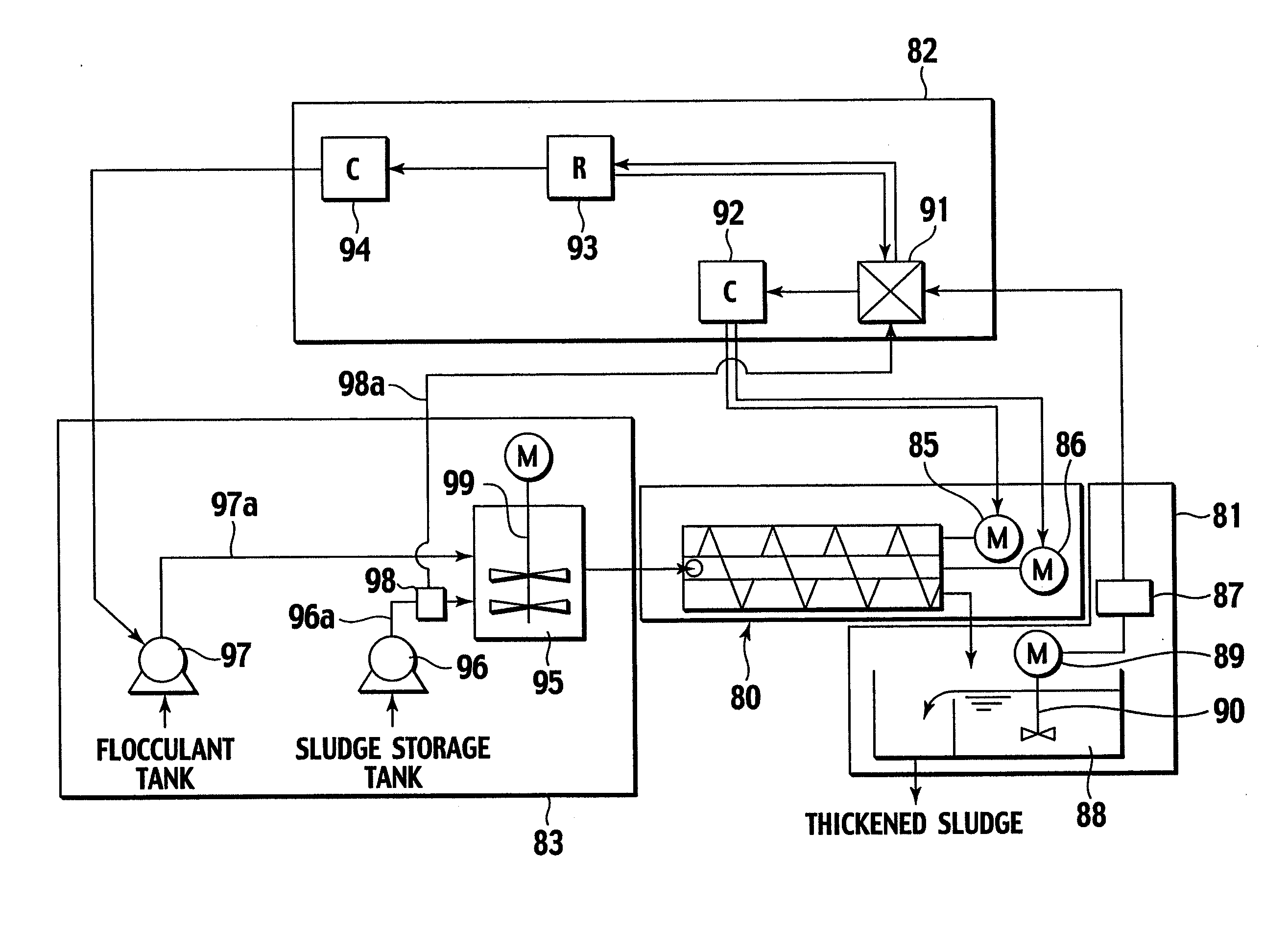
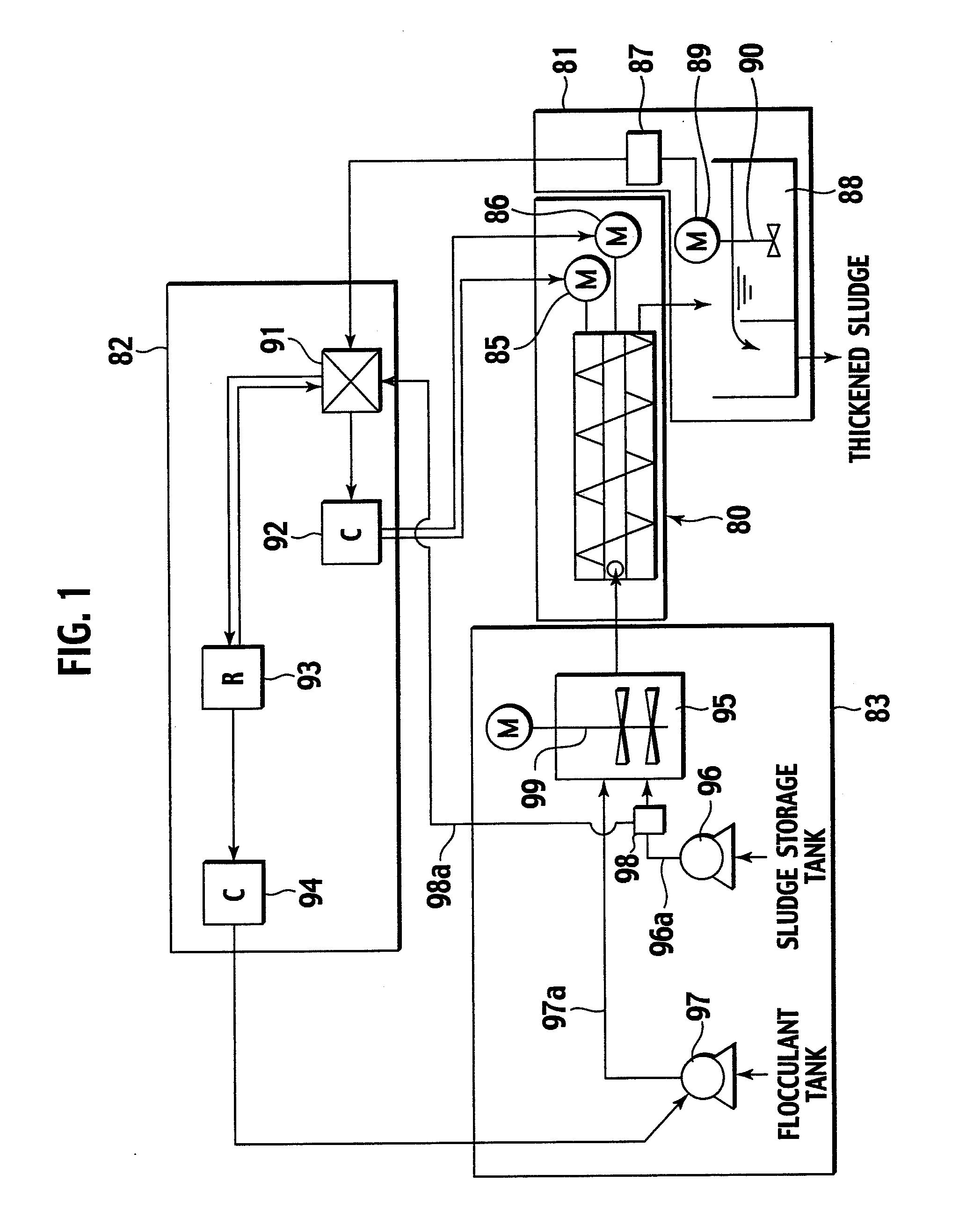
[0064]First, a constitution of the entire system of a sludge thickener is described. FIG. 1 is a block diagram of the entire sludge thickener system. A sludge thickener includes a differential rate rotary thickener 80 for thickening raw slurry sludge; a thickened-sludge-concentration detecting section 81 for detecting a thickened sludge concentration X of thickened sludge which is thickened by the differential rate rotary thickener 80 and discharged; a flocculant-feeding section 83 having a flocculant-feeding pump 97 for feeding flocculant to the raw slurry sludge; and a control section 82 for controlling the differential rate rotary thickener 80 and the flocculant-feeding pump 97 based on concentration data from the thickened-sludge-concentration detecting section 81.

[0065][Each Co...

first modified example of first embodiment

[0149]In addition, as shown in the flowchart of FIG. 11, in the above described step [1]-(e), the rotational speed C of the outer cylinder screen 21 may also be increased / decreased along with the rotational speed S of the screw 39. To be more precise, an instruction signal for simultaneously rotating the screw 39 and the outer cylinder screen 21 is sent from the discriminator 91 to the first controller 92. When the first controller 92 receives the above instruction signal, the first controller 92 simultaneously operates the screw driving machine 85 and the outer cylinder driving machine 86 so that the rotational speed S of the screw 39 is increased by an increment / decrement rotational speed a (a=1 to 2 min−1), and the rotational speed C of the outer cylinder screen 21 is decreased by the increment / decrement rotational speed b (b=1 to 2 min−1). This operation is repeatedly performed until the thickened sludge concentration X becomes less than or equal to the upper limit X max of the ...

second modified example of first embodiment

[0162]Moreover, as shown in the flowchart of FIG. 11, in the above described step [2]-(a), the rotational speed C of the outer cylinder screen 21 may also be increased / decreased along with the rotational speed S of the screw 39. To be more precise, an instruction signal for simultaneously rotating the screw 39 and the outer cylinder screen 21 is sent from the discriminator 91 to the first controller 92. The first controller 92, which has received the above instruction signal, simultaneously operates the screw driving machine 85 and the outer cylinder driving machine 86 so that the rotational speed S of the screw 39 is decreased by an increment / decrement rotational speed a (a=1 to 2 min−1), and the rotational speed C of the outer cylinder screen 21 is increased by an increment / decrement rotational speed b (b=1 to 2 min−1). This operation is repeatedly performed until the thickened sludge concentration X becomes greater than or equal to the lower limit X min of the thickened sludge co...


PUM

PropertyMeasurementUnit
speedaaaaaaaaaa
concentrationaaaaaaaaaa
rotational speedaaaaaaaaaa

Abstract

A differential rate rotary thickener; a power detector which is disposed in a sludge receiver tank for thickened sludge thickened in the differential rate rotary thickener; a discriminator which receives an electric signal for a thickened sludge concentration (X) detected by the power detector and which calculates and discriminate the data; a first controller which receives an instruction signal being a discriminated result in the discriminator and which operates an outer cylinder driving machine and a screw driving machine; a ratio setter which receives a discriminated signal of the discriminator and which increases or decreases a chemical feed rate (α) of flocculant stepwise; and a second controller which receives an instruction signal from the ratio setter and which operates a flocculant-feeding pump are provided. Thickening of sludge is performed by controlling the chemical feed rate (α), a rotational speed (S) of a screw, and a rotational speed (C) of an outer cylinder screen.

Description

TECHNICAL FIELD[0001]The present invention relates to a sludge thickening device for and a sludge thickening method of thickening sewage mixed raw sludge, sewage digested sludge, excess activated sludge, and the like, and particularly to a sludge thickening device for and a sludge thickening method of controlling an amount of flocculant added to sewage sludge, and the rotational speeds of a screw and an outer cylinder screen of a differential rate rotary thickener which performs thickening using a filtering separation method while rotating the screw and the outer cylinder screen at different speeds from each other.BACKGROUND ART[0002]A screw press has been well known as an apparatus for thickening and dehydrating sludge including organic substances of poor filtration characteristics, the screw press reducing moisture content in dehydrated sludge by adding flocculent to raw slurry including the substances and forming flocs of suspended matter, and recovering filtration surface, which...

Claims


Application Information

Patent Timeline
Patent Type & Authority Applications(United States)
IPC IPC(8): C02F11/14B01D35/14G01N15/04
CPCB01D33/11B01D37/03B30B9/12B30B9/125B30B9/26C02F1/5281C02F11/14C02F2209/003C02F2209/006C02F11/125B01D33/466C02F11/147B01D33/804Y02W10/20
Inventor SUGAYA, KENZOUKAWASAKI, HIROICHIKATAYAMA, MASAYOSHIYAMASHITA, MANABUMIYAWAKI, MASAHARU
Owner ISHIGAKI CO LTD
Why Eureka
Try Eureka