Method of Repairing Nickel-Based Alloy Articles

a nickel-based alloy and alloy disc technology, applied in the direction of manufacturing tools, soldering devices, turbines, etc., can solve the problems of high thermal stress of turbine rotor discs, high temperature and load on turbine rotors, and high centrifugal and vibratory stresses

Inactive Publication Date: 2009-03-05
GENERAL ELECTRIC CO
View PDF12 Cites 62 Cited by
  • Summary
  • Abstract
  • Description
  • Claims
  • Application Information

AI Technical Summary

Benefits of technology

[0006]In another embodiment, a method for repairing a nickel-based alloy article comprises removing a portion about a crack to expose a surface portion free of cracks in a surface of the nickel-based alloy article, wherein the article is a turbine component selected from a group consisting of moving a YAG-generated laser beam over the removed portion; providing an alloy powder to the surface portion free of cracks; and generating sufficient power to the laser to affect a fusion bond between the alloy powder and the surface portion free of cracks.

Problems solved by technology

The turbine rotor and stationary components are subject to high temperature and loading during operation.
Turbine rotor discs experience high thermal stresses during start up and shut down cycles as well as centrifugal and vibratory stresses during operation.
The high thermal stresses and cyclic operating loads can cause low and high cycle fatigue damage to turbine rotor discs.
After long term service, cracking can occur at the areas with high geometric Kt, i.e., small radii of blade attachment areas of rotor disc rim.
Nickel base alloys 706 and 718 are especially susceptible to a type of failure mode known as low cycle fatigue with hold time.
Cracks initiates under low cycle fatigue with hold time condition will continue to grow increasingly faster because of vibratory operating stresses (resulting in high cycle fatigue) until failure of the part.
Nickel based alloy turbine rotor discs are considered to be un-repairable using conventional fusion welding methods since conventional fusion welds of nickel based alloys have a large cast grain microstructure, which results in a significantly lower fatigue and hold time fatigue capabilities.
Conventional weld buildups of nickel based alloys are not capable of withstanding turbine rotor operating conditions.

Method used


Image

  • Method of Repairing Nickel-Based Alloy Articles
  • Method of Repairing Nickel-Based Alloy Articles
  • Method of Repairing Nickel-Based Alloy Articles

Examples


Embodiment Construction

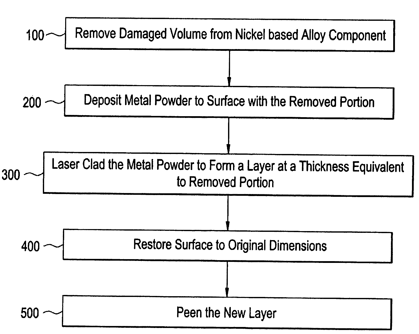
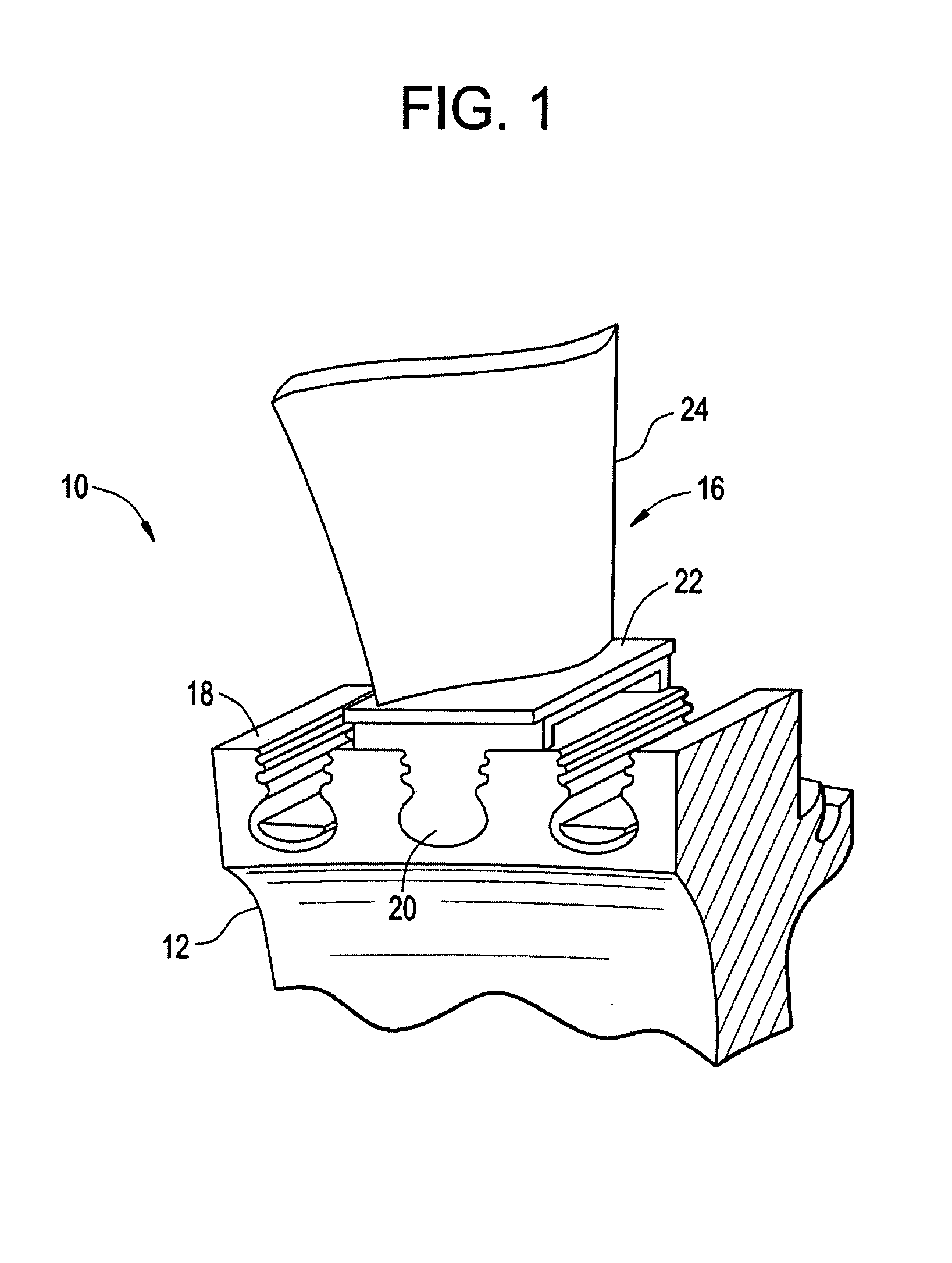
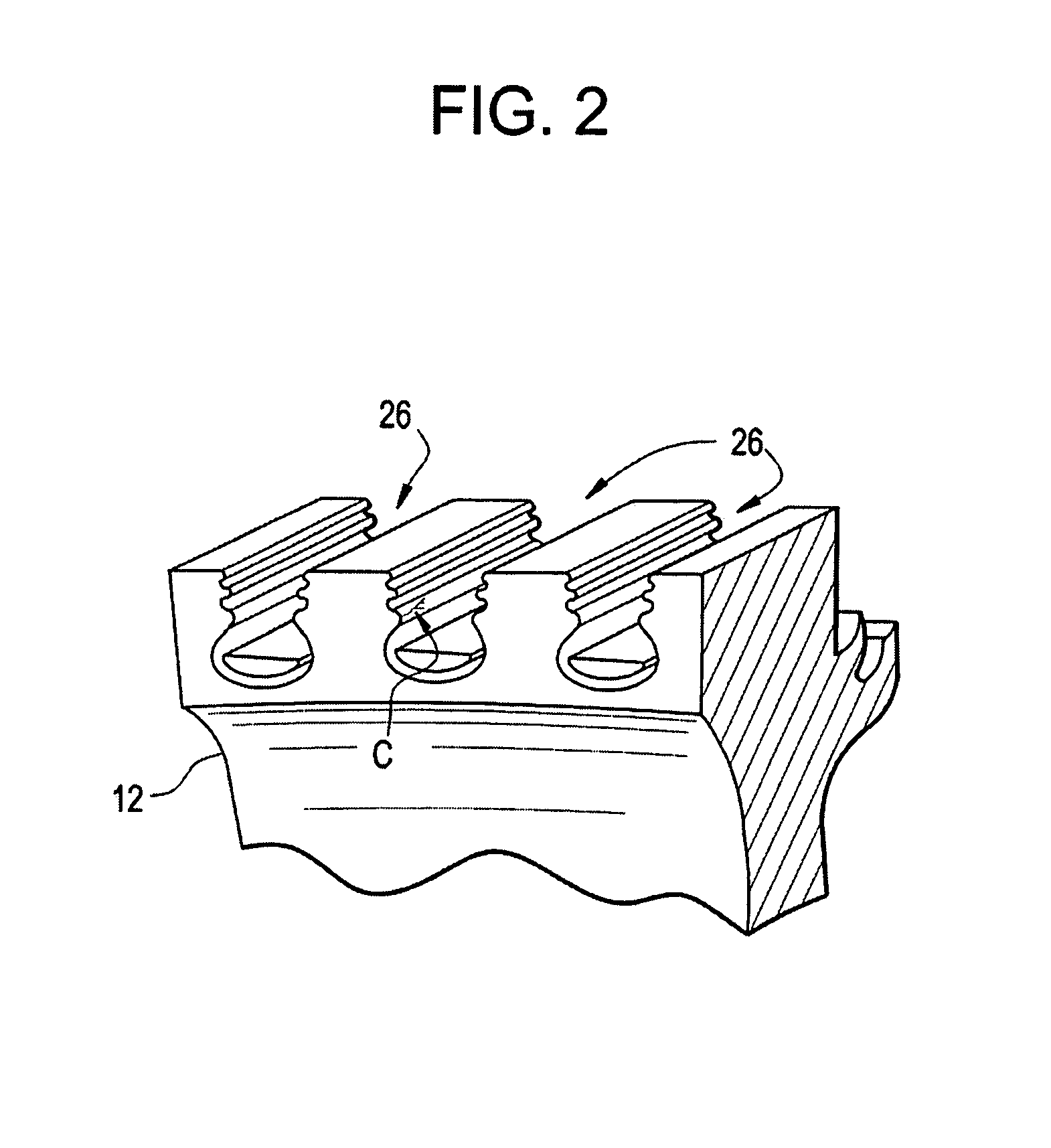
[0015]Disclosed herein is a method for repairing damaged areas, e.g., cracks, oxidized areas, and the like, in a nickel-based alloy articles such as a turbine rotor component. The method generally includes removing damaged areas (cracked and oxidized areas) with a machining process; and refilling the machined troughs (removed areas) by laser cladding with a grade ultra-fine powder metal nickel alloy, e.g., ARA 725, 718 or 706, which have mesh sizes of −150 or finer. The clad layers are free of porosities and cracks, and exhibit a homogenous fine grain microstructure (equivalent or finer than the parent metal grain size). A balanced heat input (available for powder melting and bonding, but no excess for grain growth and dilution / alloying), multiple-pass laser cladding process is developed to produce uniform, rapidly solidified and cooled buildup layers that have a fine grain microstructure; and the process gives rise to a minimal distortion of the original component.

[0016]In this met...


PUM

PropertyMeasurementUnit
melting pointaaaaaaaaaa
diametersaaaaaaaaaa
diametersaaaaaaaaaa

Abstract

Methods for repairing nickel based alloy articles such as gas turbine rotors generally includes a removing a damaged portion of the articles and laser cladding a high temperature nickel based alloy powder thereto to form a solid layer. The process can be repeated until a desired thickness is obtained. Optionally, a peening process subsequent to laser cladding can be implemented to introduce compressive stress to the solid layer formed by laser cladding.

Description

BACKGROUND OF THE INVENTION[0001]The present disclosure generally relates to the repair of nickel-based alloy articles, more specifically, to the repair of nickel based alloy rotor discs used in the operation of gas and / or steam turbine systems.[0002]In gas turbines, air is drawn into the front of the turbine, compressed by a compressor, and mixed with fuel. The mixture is combusted, and the resulting hot combustion gas is passed through the turbine. The turbine includes a rotor with turbine blades supported on its periphery, and a stationary portion (that is, not rotating) mainly consisting of nozzles to direct gas flow and shrouds to radially confine the gas flow. The combustion gas flows through the annulus between the rotor and the shrouds and drives rotation of the turbine blades. The constrained flow of hot combustion gas turns the turbine rotor by driving an airfoil portion of the turbine blades, which turns the turbine rotor and provides output to a generator. The turbine ro...

Claims


Application Information

Patent Timeline
Patent Type & Authority Applications(United States)
IPC IPC(8): B23K26/34
CPCB22F7/064B23K2201/001B23P6/007C22C1/0433C22C19/055B23K35/0244C22C19/058F01D5/005F05D2230/80B23K26/3213B23K26/345C22C19/056B23K26/32B23K26/342B23K2101/001B23K2103/26
Inventor CHEN, JIANQIANGJACKSON, JOSEPH JAY
Owner GENERAL ELECTRIC CO
Why Eureka
Try Eureka