
Dual Band Stacked Patch Antenna

a patch antenna and dual band technology, applied in the field of patch antennas, can solve the problems of reducing the overall performance of each antenna, not providing a desirable amount of vlp gain for terrestrial sdars signals, and often affecting the performance of the two antennas, so as to reduce the final assembly time, reduce manufacturing costs, and simplify the effect of construction

Inactive Publication Date: 2009-03-05
GM GLOBAL TECH OPERATIONS LLC
View PDF8 Cites 270 Cited by
  • Summary
  • Abstract
  • Description
  • Claims
  • Application Information

AI Technical Summary

Benefits of technology

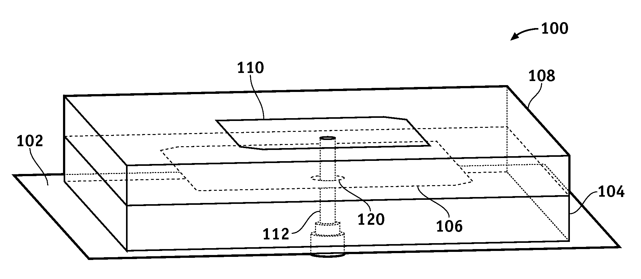
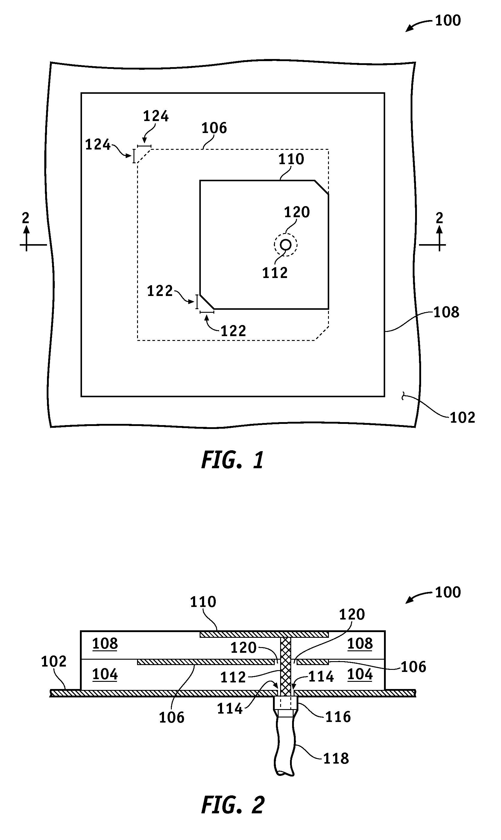
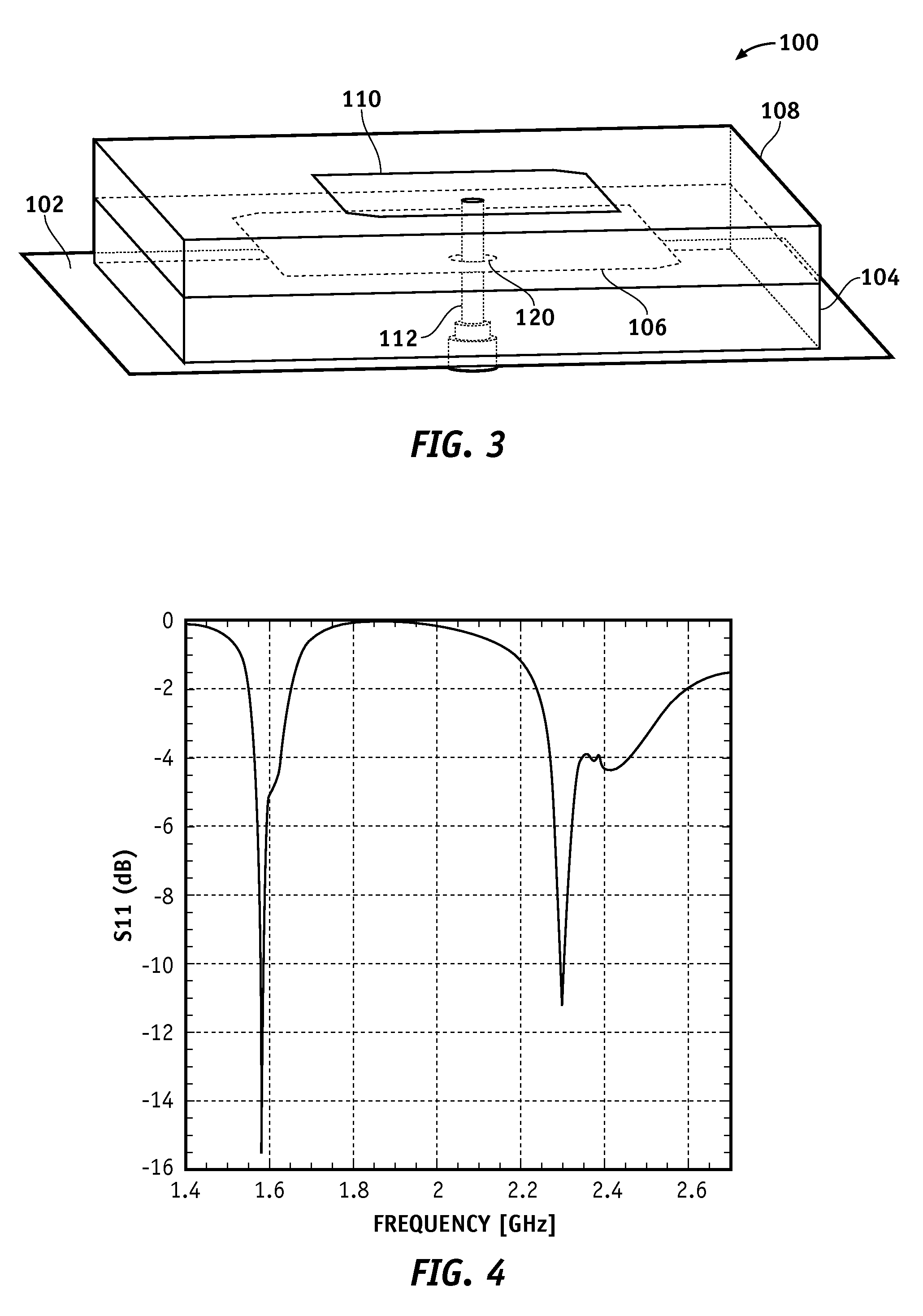
[0005]A dual band patch antenna as described herein includes a stacked arrangement of two radiating elements separated by dielectric material. Both radiating elements share the same conductive feed, which may simplify the construction, reduces manufacturing cost, and reduces final assembly time. In one embodiment suitable for use in vehicular deployments, the dual band patch antenna can be configured and tuned to receive RHCP GPS signals simultaneously with LHCP SDARS signals. This particular dual band patch antenna is at the same time also configured and tuned to provide enhanced gain for terrestrial VLP SDARS signals.

Problems solved by technology

Unfortunately, undesirable coupling often occurs between the two antennas when they are placed close to one another, which is often the case in vehicle installations that strive to achieve a streamlined and clean appearance.
Such coupling degrades the overall performance of each antenna, particularly the VLP terrestrial gain in the SDARS frequency band (in addition, typical standalone SDARS patch antennas do not provide adequate VLP gain for reliable quality of service).
This first design may not provide a desirable amount of VLP gain for terrestrial SDARS signals.
This second design has the disadvantage of having a relatively complex configuration, and the further disadvantage of requiring two distinct feed elements, which increases the complexity and cost of final assembly onto a vehicle.

Method used


Image

  • Dual Band Stacked Patch Antenna
  • Dual Band Stacked Patch Antenna
  • Dual Band Stacked Patch Antenna

Examples


Embodiment Construction

[0021]The following detailed description is merely exemplary in nature and is not intended to limit the invention or the application and uses of the invention. Furthermore, there is no intention to be bound by any expressed or implied theory presented in the preceding technical field, background, brief summary or the following detailed description.

[0022]For the sake of brevity, conventional techniques and aspects related to GPS systems, SDARS systems, RF / microwave antenna design, and RF / microwave signal propagation may not be described in detail herein. In addition, those skilled in the art will appreciate that embodiments of the dual band patch antennas described herein may be practiced in conjunction with any number of applications and installations at any set of two or more frequency bands, and that the vehicular deployment described herein is merely one suitable example.

[0023]The following description refers to elements or nodes or features being “connected” or “coupled” togethe...


PUM


Abstract

One or more of the embodiments of a dual band stacked patch antenna described herein employ an integrated arrangement of a global positioning system (GPS) antenna and a satellite digital audio radio service (SDARS) antenna. The dual band antenna receives right hand circularly polarized GPS signals in a first frequency band, left hand circularly polarized SDARS signals in a second frequency band, and vertical linear polarized SDARS signals in the second band. The dual band antenna includes a ground plane element, an upper radiating element (which is primarily utilized to receive SDARS signals), dielectric material between the ground plane element and the upper radiating element, and a lower radiating element (which is primarily utilized to receive GPS signals) surrounded by the dielectric material. The dual band antenna uses only one conductive signal feed to receive both GPS and SDARS signals.

Description

TECHNICAL FIELD[0001]The subject matter described herein generally relates to patch antennas, and more particularly relates to an integrated dual band stacked patch antenna that is suitable for use with both global positioning system (GPS) signals and satellite digital audio radio service (SDARS) signals.BACKGROUND[0002]The prior art is replete with radio frequency (RF) and microwave antenna designs, structures, and configurations. Such antennas are utilized in many different applications to wirelessly transmit and receive signals that convey information or data. For example, modern automobiles (and other vehicles) might utilize a number of antennas that receive signals throughout the RF spectrum. Indeed, a vehicle may include one or more of the following systems: an AM / FM radio; a satellite radio; a GPS based navigation system; and a mobile telecommunication system. Some vehicles may include antennas to receive SDARS signals and / or GPS signals. In this context, L1 GPS signals are u...

Claims


Application Information

Patent Timeline
IPC IPC(8): H01Q9/04H01Q5/10H01Q5/378
CPCH01Q5/378H01Q9/0414
Inventor GEARY, KEVINSCHAFFNER, JAMES H.HSU, HUI-PINCOLBURN, JOSEPH S.SONG, HYOK J.
Owner GM GLOBAL TECH OPERATIONS LLC
Learn More