[0006]In one embodiment, a
balloon cannula
system (access system) is fitted with an
extrusion (e.g. deflated balloon material) that is terminally bonded. Following positioning of the balloon cannula system at the targeted site to be treated, the balloon may be inflated and may be used as an atraumatic tool for
dissection and / or an atraumatic tool to create
working space, thereby enhancing visualization of the surrounding structures. In one embodiment, the balloon is a forward-looking structure so that the distal tip of the balloon may push obstructive tissue away from the scope, and the distal tip of the balloon may provide a depth of view between the scope and the targeted sites to be treated.
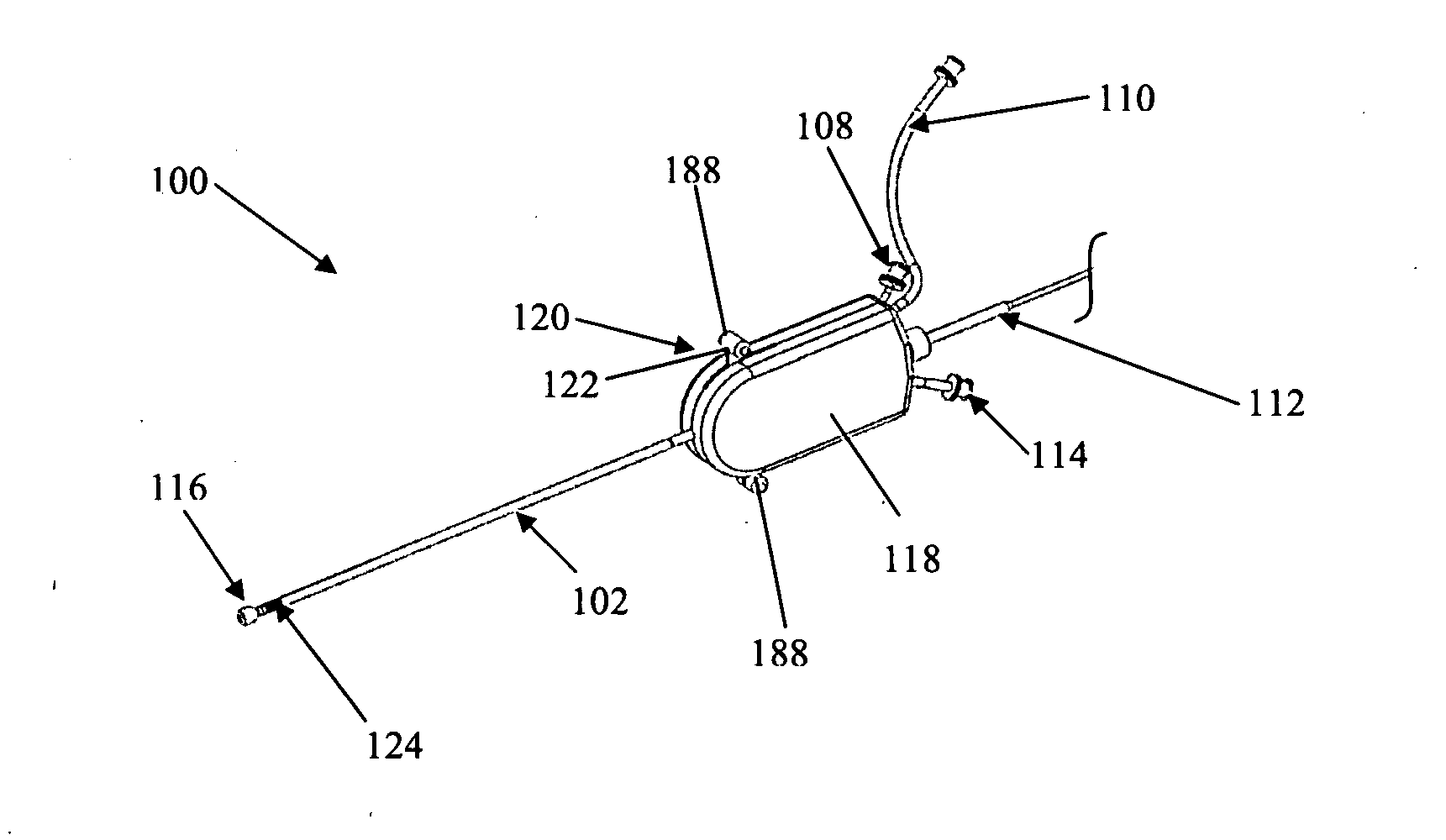
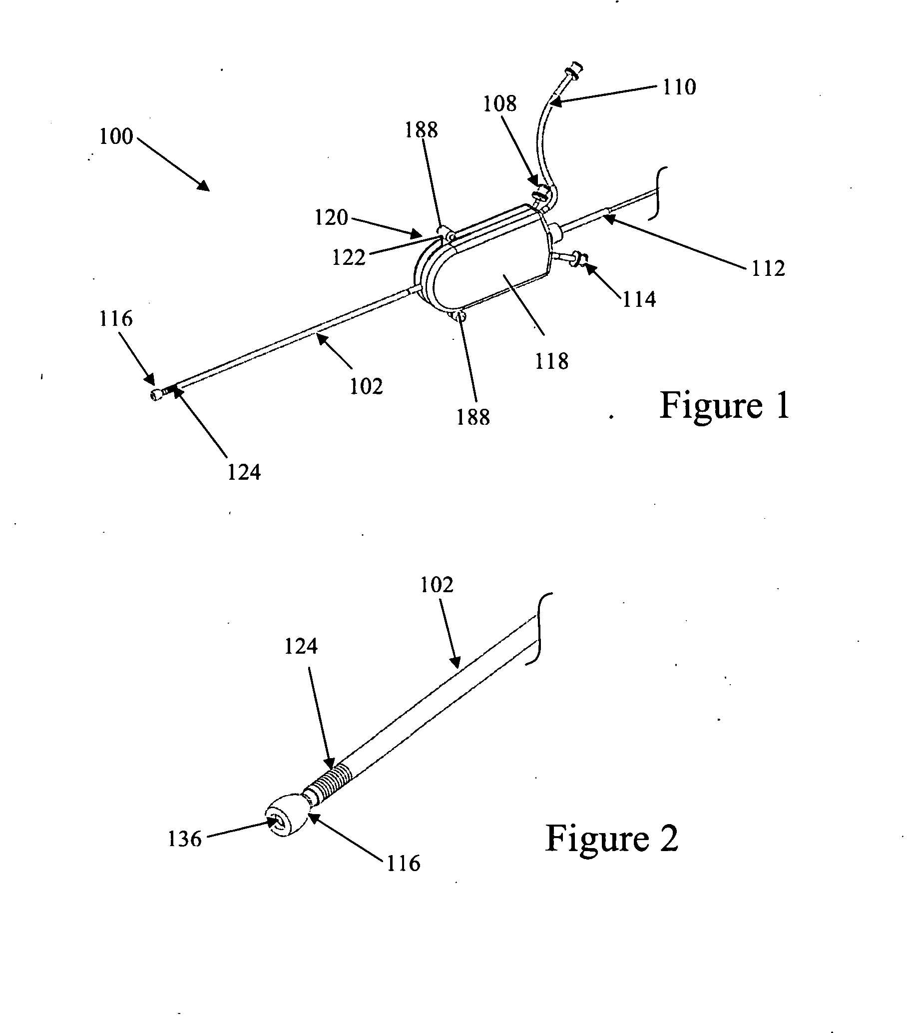
[0007]One embodiment is directed to a balloon
cannula device comprising a multi-lumen elongated shaft, a balloon attached at its distal end of the shaft, wherein the proximal end of the balloon and distal end of the balloon are attached to the outer surface of the same elongated shaft, and wherein the balloon is constructed such that following inflation of the balloon, said balloon is forward-looking to create a
working space distally to the viewing scope to enhance direct visualization. In another embodiment, the balloon of the balloon cannula system includes at least one portion that is elastically expandable. The expandable balloon may be inflated with air, sterile
saline, contrasting agent, or other agents that may be delivered via a
syringe or a pump. In some embodiments, the balloon is able to simultaneously undergo radial expansion and keep the forward-looking feature of the balloon cannula system. In one or more of the embodiments described herein, the distance between the points of attachment of the balloon to the same outer shaft of the elongated shaft is between about 1 mm and about 15 mm. In another embodiment, one end of the balloon is attached to a distal end of the
balloon catheter in a flipped manner (e.g. everted or inverted), such that the internal surface of the balloon is in contact with the elongated shaft distally, and the outer surface of the balloon is in contact with the same elongated shaft proximally. In yet another embodiment, the balloon includes at least one elastically deformable portion. In yet another embodiment, the deformable portion is constructed of
polyurethane.
[0010]In one embodiment, a method for treating
intervertebral disc degeneration in a spine includes introducing a balloon
cannula device that permits direct visualization capability into a portion of the spine, inflating the balloon cannula to create a forward-looking capability to enhance visualization and displacement of tissues, and introducing a therapy device into the balloon
cannula device to treat
disc degeneration.
[0011]In another embodiment, a method for treating
intervertebral disc degeneration in a spine of a body includes making an incision into a
skin of the body, introducing a balloon cannula device that permits direct visualization into a portion of the spine, inflating the balloon cannula to create a forward-looking capability that enhances visualization and displacement of tissues, introducing a therapy device into balloon cannula device to treat
disc degeneration, and treating the disc degeneration.
[0017]In another embodiment, a balloon cannula device for assessing a
target site within the body may include a multi-lumen elongated shaft and a balloon attached at a distal end of the shaft, wherein the proximal end and distal end of the balloon are attached to the outer surface of the elongated shaft and wherein the balloon is constructed such that following inflation of the balloon, the balloon is forward-looking and create a working space distally to the viewing scope to enhance direct visualization.
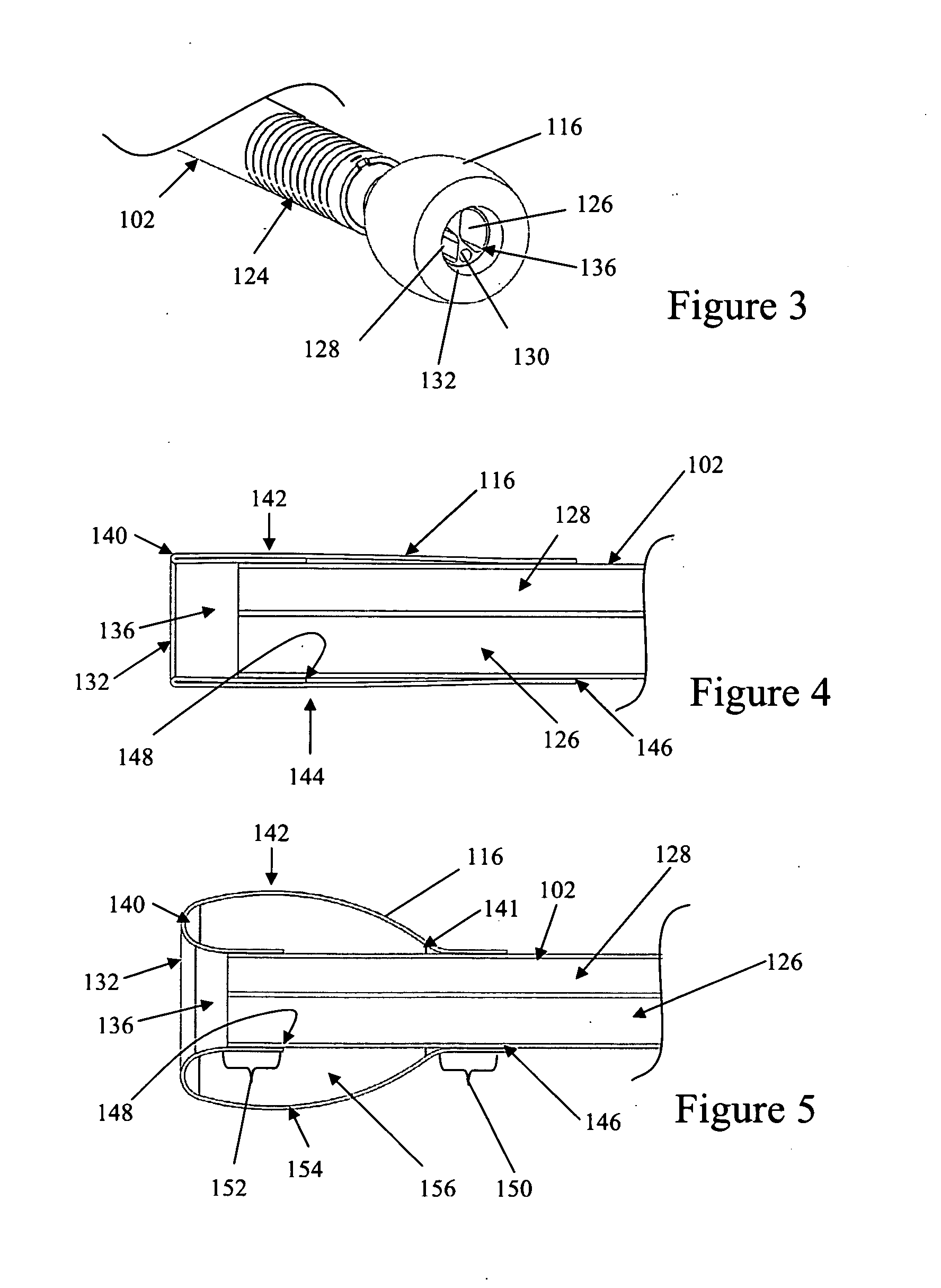
[0018]In another embodiment, a balloon cannula device for visualizing a
target site within body may include a proximal portion and a
distal portion, at least three lumens positioned within the proximal portion, wherein at least one lumen is suitable for allowing the passage of
endoscope, at least one lumen is suitable for inflation of a balloon, and at least one lumen is suitable for allowing passage of therapeutic instruments or injection of medications. In some embodiments, at least two lumens may be positioned within the distal end, and at least one of the lumens permits visualization of therapeutic instruments or injected medications. A balloon may be attached to an outer surface of the
distal portion of the balloon cannula device, and at least part of the
distal portion of the balloon cannula device may be constructed such that following inflation of the balloon, the balloon is forward-looking to create a working space distally to enhance direct visualization. In one or more of the embodiments described herein, the balloon is constructed of
polyurethane, but in other embodiments may be constructed of a
polymer material other than
polyurethane.

