
Separator for electrochemical device and method for producing the same, and electrochemical device and method for producing the same

Active Publication Date: 2009-03-12
MAXELL HLDG LTD
View PDF29 Cites 100 Cited by
  • Summary
  • Abstract
  • Description
  • Claims
  • Application Information

AI Technical Summary

Benefits of technology

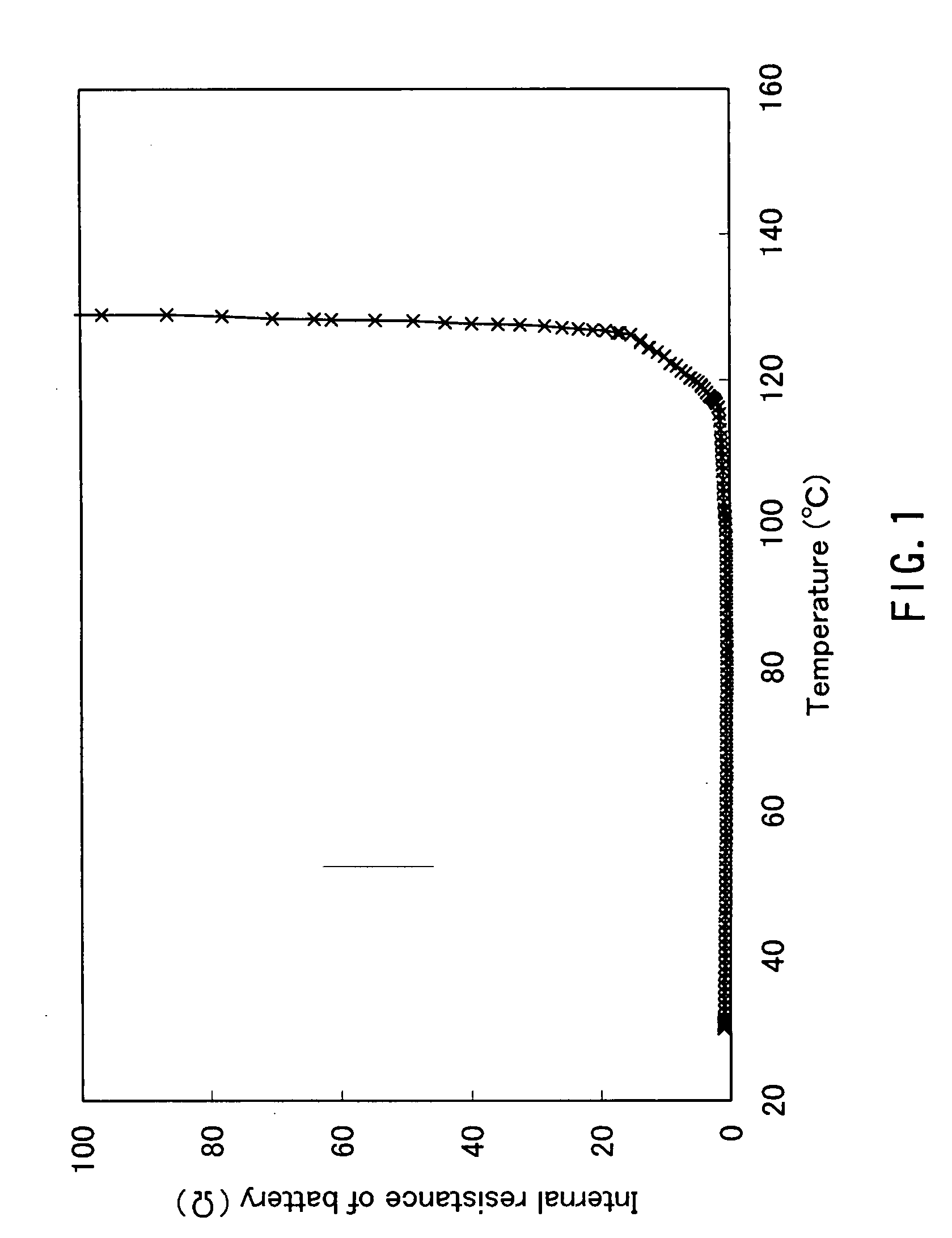
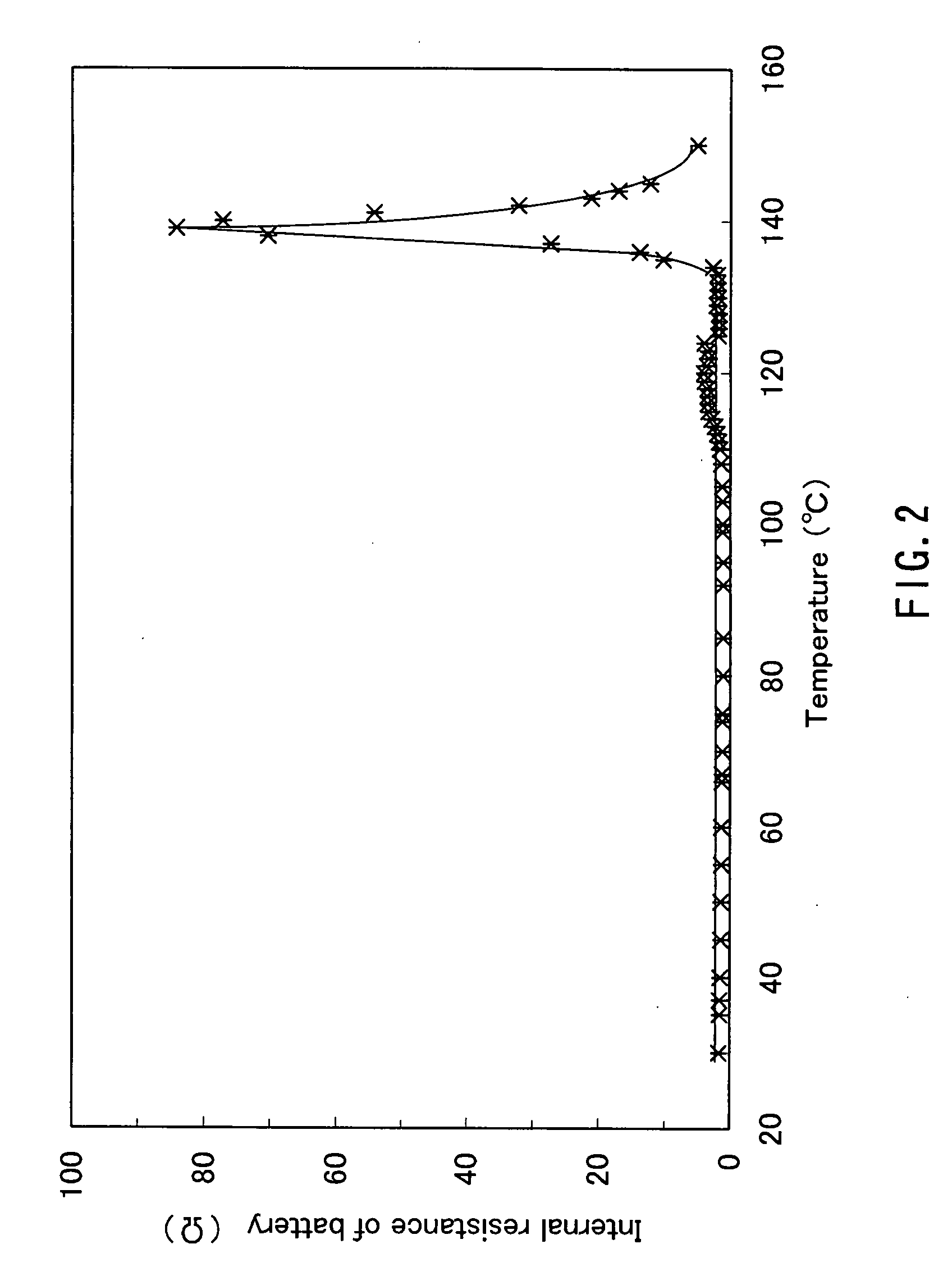
[0019]According to the present invention, an electrochemical device, which is excellent in reliability with respect to an internal short-circuit caused by various causes and in safety when the battery temperature rises abnormally due to a short-circuit or overcharge, can be provided.

Problems solved by technology

However, since crystallinity of the stretched film is increased, and the shutdown temperature is raised up to approximately the thermal runaway temperature of the battery, the margin for securing the safety of the battery cannot be provided sufficiently.
Moreover, distortion occurs in the film due to the stretching, and thus when exposed to a high temperature, shrinkage will occur due to residual stress.
If the pores are not closed sufficiently and the current cannot be decreased immediately, the battery temperature will be raised easily to the shrinking temperature of the separator, causing a risk of abnormal heating due to an internal short-circuit.
Though each of the above-mentioned separators made of a heat-resistant resin or heat-resistant fibers has excellent dimensional stability at a high temperature and can be made thinner, it does not have the so-called shutdown characteristic, namely, a characteristic that the pores will be closed at a high temperature, and thus the separator cannot provide sufficient safety at an abnormality, specifically when the battery temperature rises rapidly due to an external short-circuit or an internal short-circuit.
However, studies of the present inventors have shown that the above-described separators have a problem in securing the reliability of a battery for the following reason.
However, such a separator is not provided with the shutdown function, and thus has a problem in securing safety.
However, according to studies of the present inventors, when lithium dendrite is formed, the dendrite is likely to penetrate a porous film formed of granular inorganic fine particles, and thus the reliability with respect to an internal short-circuit caused by the dendrite cannot be secured sufficiently.
However, when a positive electrode, a negative electrode, and the separator are wound spirally to form a wound body, which generally is used for a lithium battery, the separator formed of the inorganic filler easily cracks, which may cause a short-circuit.
Especially, in the case of a rectangular battery using a wound body having a bent portion of a small diameter, the problem of a short-circuit caused by a crack of the separator is notable.

Method used


Image

  • Separator for electrochemical device and method for producing the same, and electrochemical device and method for producing the same
  • Separator for electrochemical device and method for producing the same, and electrochemical device and method for producing the same

Examples


production example 1

Production of Negative Electrode

[0117]95 mass parts of graphite as a negative active material and 5 mass parts of PVDF as a binder were mixed homogeneously in a solvent of NMP so as to prepare a paste containing a negative mixture. This paste containing a negative mixture was applied intermittently on both faces of a copper foil 10 μm in thickness for making a current collector so that the length of the applied active material was 320 mm on the surface and 260 mm on the back face, which was dried subsequently. Later, calendering was carried out for adjusting the thickness of the negative mixture layer so that the entire thickness would be 142 μm, which was then cut to be 45 mm in width, and thus a negative electrode 330 mm in length and 45 mm in width was produced. Further, a tab was welded to an exposed part of the copper foil of this negative electrode so as to form a lead portion.

production example 2

Production of Positive Electrode

[0118]85 mass parts of LiCoO2 as a positive active material, 10 mass parts of acetylene black as a conductive auxiliary, and 5 mass parts of PVDF as a binder were mixed homogeneously in a solvent of NMP so as to prepare a paste containing a positive mixture. This paste was applied intermittently on both faces of an aluminum foil 15 μm in thickness for making a current collector so that the length of the applied active material was 319 to 320 mm on the surface and 258 to 260 mm on the back face, which was dried subsequently. Later, calendering was carried out for adjusting the thickness of the positive mixture layer so that the entire thickness would be 150 μm, which was then cut to be 43 mm in width, and thus a positive electrode 330 mm in length and 43 mm in width was produced. Further, a tab was welded to an exposed part of the aluminum foil of this positive electrode so as to form a lead portion.

example 1

[0119]An aqueous dispersion (solid content: 40 mass %) [liquid composition (1-A)] of PE fine particles (average particle diameter: 1 μm; melting point: 125° C.) was applied on both faces of the negative electrode produced in Production Example 1 by a blade coater, which was dried subsequently. As a result, a first separator layer based on the PE as resin A was formed to have a thickness of 5 μm. In the same manner, the first separator layer based on the PE fine particles as resin A having a thickness of 5 μm also was formed on both faces of the positive electrode produced in Production Example 2. The first separator layer formed on the positive electrode and the negative electrode was formed only of the PE fine particles as resin A, and thus the content of the resin A in the first separator layer was 100% by volume.

[0120]2000 g of an aqueous dispersion (solid content: 40 mass %) of PE fine particles (average particle diameter: 1 μm; melting point: 125° C.) and 800 g of ethanol were ...


PUM

PropertyMeasurementUnit
Temperatureaaaaaaaaaa

Abstract

An electrochemical device having excellent safety at a high temperature is provided by using a separator for an electrochemical device, which is made of a porous film including a first separator layer and a second separator layer. The first separator layer includes, as a main ingredient, at least one kind of resin selected from the group consisting of resin A that has a melting point in a range of 80° C. to 130° C., and resin B that absorbs a nonaqueous electrolyte and swells due to heating and whose swelling degree is increased as the temperature rises, the second separator layer includes, as a main ingredient, a filler that has a heat-resistant temperature of not lower than 150° C., and at least one of the first separator layer and the second separator layer includes flakes.

Description

TECHNICAL FIELD[0001]The present invention relates to a separator for an electrochemical device provided at a low cost and having excellent dimensional stability at a high temperature, and also an electrochemical device using the separator and being safe even in a high-temperature environment.BACKGROUND ART[0002]Electrochemical devices using nonaqueous electrolytes, represented by a lithium secondary battery and a supercapacitor, have been used widely as power sources for portable equipment such as mobile phones and notebook-sized personal computers because of the characteristic of high energy density. With improvement in the performance of the portable equipment, the capacity of the electrochemical devices tends to become higher, and thus securing safety has become important.[0003]In a current-technology lithium secondary battery, a polyolefin-based porous film having a thickness of 20 to 30 μm is used as a separator to be interposed between a positive electrode and a negative elec...

Claims


Application Information

Patent Timeline
IPC IPC(8): H01M10/50B05D5/12H01G9/15H01G11/00H01G11/14H01G11/22H01G11/52H01M4/50H01M4/505H01M4/52H01M4/525H01M10/0566H01M10/0568H01M10/058H01M50/403H01M50/417H01M50/42H01M50/429H01M50/449H01M50/489H01M50/491
CPCH01G9/02H01M2/145H01M2/162H01M2/1626Y10T29/417H01M2/1686H01M6/181H01M10/052H01M10/0565H01M2/1653H01M4/505H01M4/525H01M6/14H01M6/166H01M10/0568H01M10/4235Y02E60/10H01M50/403H01M50/44H01M50/4295H01M50/449Y02P70/50H01M50/429H01M50/417H01M50/491H01M50/489H01M50/42H01M10/05H01M50/411Y02E60/13
Inventor KATAYAMA, HIDEAKIABE, TOSHIHIROMATSUMOTO, NOBUAKISATO, YOSHINORI
Owner MAXELL HLDG LTD
Learn More