
Method of forming light-scattering dots inside the diffusion plate and light guide plate by laser engraving

a technology of diffusion plate and light guide plate, which is applied in the field of light diffusion plate, can solve the problems of confined improvement, poor luminance performance of this design, and increase the weight, thickness and power consumption of the whole lcd module, and achieve the effect of improving the uniformity of luminance of the lcd panel

Inactive Publication Date: 2009-03-12
KISMART
View PDF4 Cites 76 Cited by
  • Summary
  • Abstract
  • Description
  • Claims
  • Application Information

AI Technical Summary

Benefits of technology

[0009]Laser engraving is the process of producing the fine grooves or cracks on the substrate to form the characters or objects. This technique utilizes the material (such as crystal or PMMA) with transparency and high refractive index to form internal pattern or images. Laser engraving is free of the surface residues and does not require post process polishing. Also, the 2-dimentional or 3-dimentional manipulation with laser engraving is relatively easy. Therefore, it is an excellent method to form accurate dot pattern distribution inside the transparent material.
[0010]One embodiment in the present invention is provided with a method of forming internal scattering dots within a diffusion plate by laser engraving. The density distribution of the scattering dots engraved therein is in the form of Gauss distribution whose minimum is aligning to the midpoint between the light sources disposed under the diffusion plate, and whose maximum is aligning to the position of light sources. The density distribution of scattering dots in this embodiment can compensate the non-uniform distribution of luminance in corresponding position to improve the luminance uniformity on the LCD panel and resolve the lamp mura issue. Besides, forming scattering dots inside the diffusion plate can also increase the whole luminance of the LCD panel.
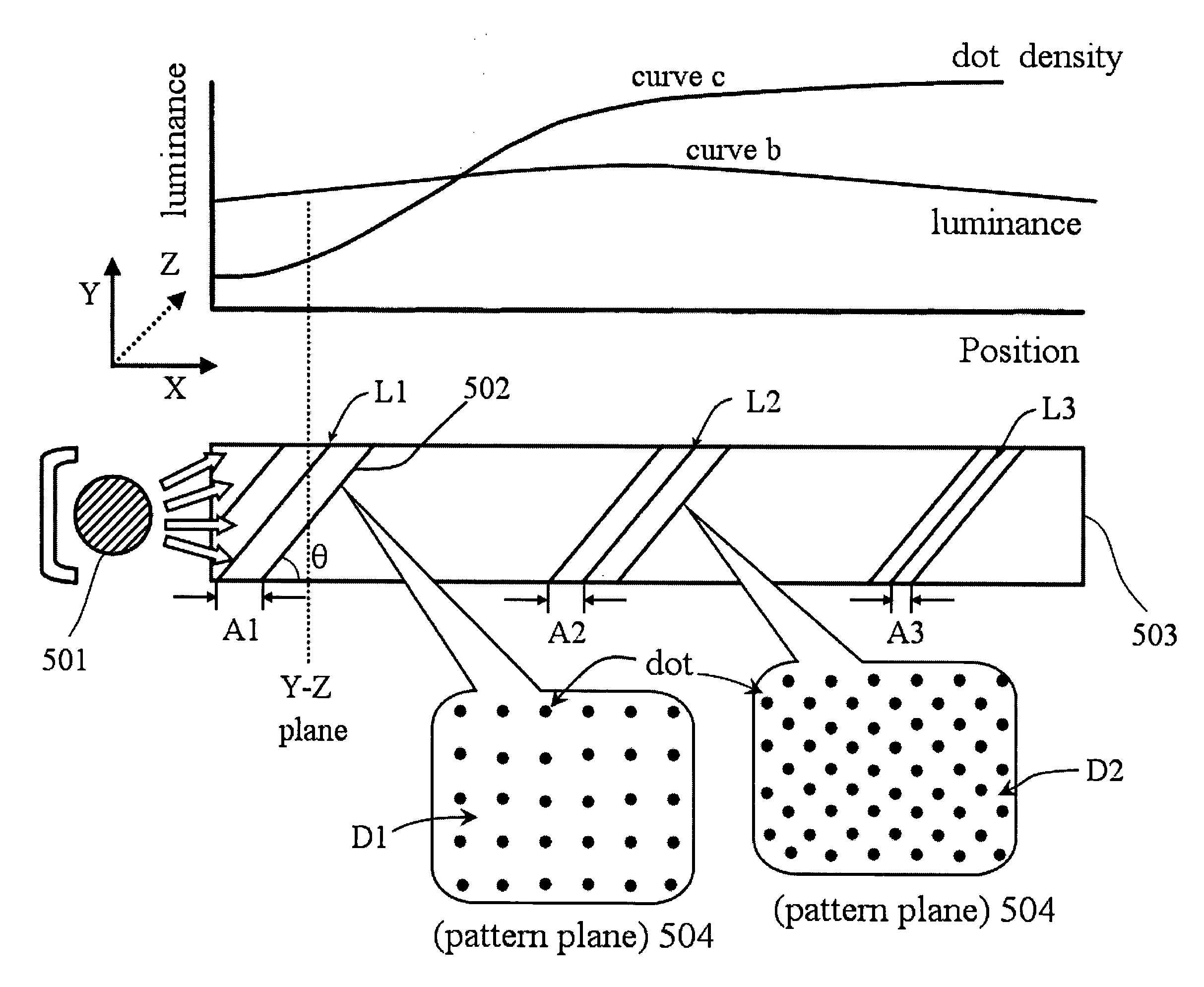
[0013]In still another embodiment in the present invention, a method is provided to forming internal scattering dots within a light guide plate by laser engraving, wherein the internal scattering dots can be arranged on a plurality of pattern plane space-aparted and / or parallel from each other. The dot density of said pattern planes and the pitch between said pattern planes can be modulated cooperatively or respectively depending on the original luminance distribution of the light guide plate. The density distribution of scattering dots in this embodiment can compensate the non-uniform distribution of luminance in corresponding position to improve the luminance uniformity on the LCD panel and resolve the mura issue. Besides, forming scattering dots inside the light guide plate can also increase the whole luminance of the LCD panel.
[0014]In still another embodiment in the present invention, a method is provided to form internal scattering dots within a light guide plate by laser engraving, wherein the internal scattering dots are arranged on a plurality of sinusoidal curve which propagate along the light guide plate. The dot density and cycle distance of the sinusoidal curves can be modulated cooperatively or respectively depending on the original luminance distribution of said light guide plate. The density distribution of scattering dots in this embodiment can compensate the non-uniform distribution of luminance in corresponding position to improve the luminance uniformity on the LCD panel and resolve the mura issue. Besides, forming scattering dots inside the light guide plate can also increase the whole luminance of the LCD panel.
[0016]Another object of present invention is to provide a method for improving the luminance uniformity of diffusion plate and light guide plate by laser engraving.
[0018]The laser engraving method provided in present invention can also coordinate with other diffusion technique such as ink printing, diffusion particles and micro structure, etc, to further improve the luminance uniformity of the LCD panel.

Problems solved by technology

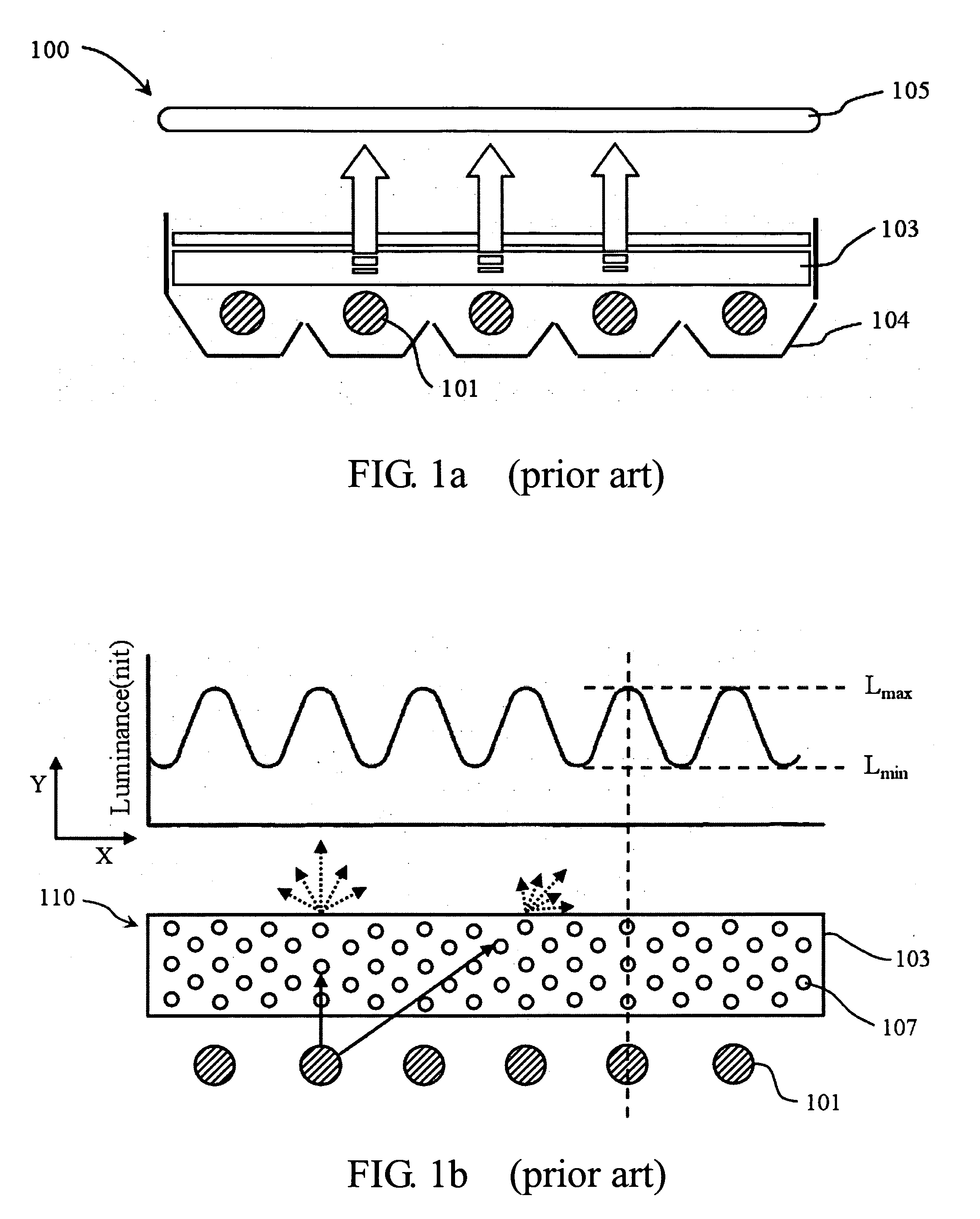
Because there are sufficient room under the diffusion plate 103 for lamp disposition, the direct-light type backlight module can be provided with two or more lamp tubes (or numerous LED light source disposed in array) depending on the size of LCD panel, but this also increases the weight, thickness and power consumption of the whole LCD module.
Though the diffusion plate 103 is used in direct-type backlight module to improve the luminance uniformity of LCD panel, the luminance performance of this design is still worse.
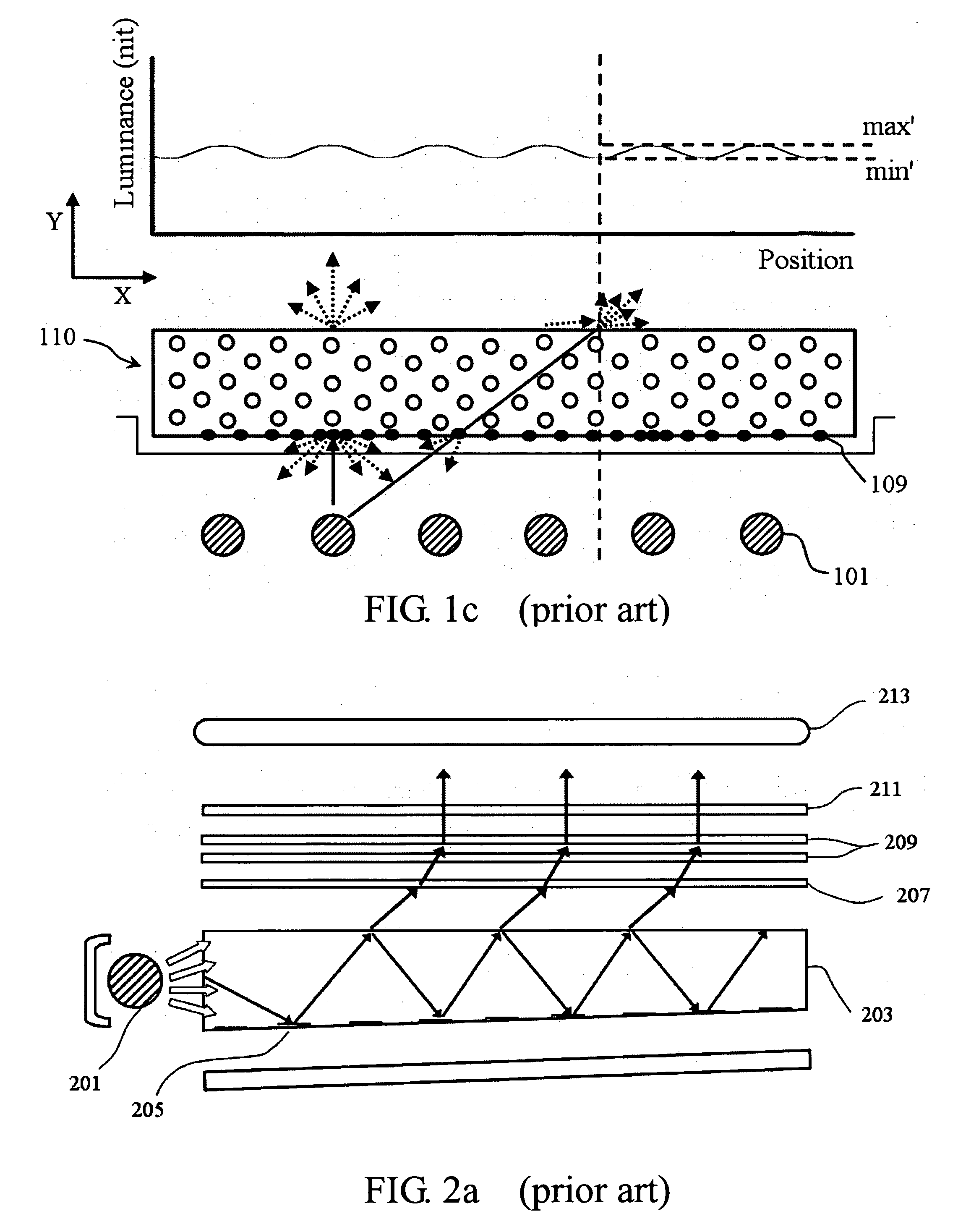
Though the method of forming micro structure in specific pattern on the bottom of diffusion plate can obtain better uniformity of luminance than the method in FIG. 1b (i.e. the difference of Lmin and Lmin in FIG. 1c is smaller than that in FIG. 1b), its improvement is still confined due to the distribution of dot pattern can only be two dimensional.
Though V-cut light guide plate has some advantages, it still suffers the uniformity issue.
Rather than the uniform luminance, the manufacture of V-cut light guide plate needs mold opening process, which requires extra time and cost to develop.
Furthermore, the transcription quality for V-cut structure is another issue to consider.

Method used


Image

  • Method of forming light-scattering dots inside the diffusion plate and light guide plate by laser engraving
  • Method of forming light-scattering dots inside the diffusion plate and light guide plate by laser engraving
  • Method of forming light-scattering dots inside the diffusion plate and light guide plate by laser engraving

Examples


Embodiment Construction

[0031]The invention will now be described in greater detail with preferred embodiments of the invention and illustrations attached. Nevertheless, it should be recognized that the preferred embodiments of the invention is only for illustrating. Besides the preferred embodiment mentioned here, present invention can be practiced in a wide range of other embodiments besides those explicitly described, and the scope of the present invention is expressly not limited expect as specified in the accompanying Claims.

[0032]Referring first to FIG. 2c, which illustrates the cross-section view of a light guide plate with V-cut microstructure and laser engraving dots in the embodiment of present invention. In the figure, a light guide plate 203 is provided with V-cut microstructure 215 on the bottom surface thereof. A light source 201 is disposed at the lateral side of light guide plate 203. The distance A in FIG. 2c is identical to the distance A in FIG. 2b, which indicates the area where the kid...


PUM

PropertyMeasurementUnit
Sizeaaaaaaaaaa
Densityaaaaaaaaaa
Microstructureaaaaaaaaaa

Abstract

The present invention discloses a method of forming internal scattering pattern in the diffusion plate and light guide plate used in backlight module by laser engraving. In the present invention, the distribution and density of the engraved dots can be controlled and modulated depending on the position of the light source and the distribution of luminance to obtain higher luminance and better luminance uniformity.

Description

FIELD OF THE INVENTION[0001]The present invention generally relates to a light diffusion plate, more particularly relates to a diffusion plate and light guide plate (LGP) with laser engraving pattern formed therein to improve the uniformity of luminance and brightness thereof.DESCRIPTION OF THE PRIOR ART[0002]Up to this day, TFT-LCD (thin film transistor liquid crystal displayer) has replaced CRT (cathode-ray tube) displayer on a mass scale no matter in the field of computer, consumer or communication electronics. Substantially, TFT-LCD has the characteristics of thinner thickness, lighter weight, accompanied with the advantage of lower radiation compared to the conventional CRT displayer, thus TFT-LCD panel can be well-accommodated to the current popular electronic products such as notebook, PDA, cellphone, digital camera, flat panel TV, projector and digital photo frame that full of commercial potential in current 3C industry. Stimulated by the low price of LCD panel and the deman...

Claims


Application Information

Patent Timeline
IPC IPC(8): F21V5/00B23K26/00
CPCG02B5/0242G02B5/0263G02B5/0278G02B6/0065G02B6/0051G02B6/0061G02B6/0041
Inventor HUANG, HSIN-TAOHSIAO, CHUN-CHUNG
Owner KISMART
Learn More