
Movable body drive method and movable body drive system, and pattern formation method and pattern formation apparatus

a technology of movable bodies and drives, applied in the direction of printing, instruments, measurement devices, etc., can solve the problems of difficult positioning of multipoint af systems in the vicinity of projection optical systems, risk of focus margin shortage, and surface of wafer serving as a substrate subject to exposure, etc., to achieve good precision, improve alignment precision, and improve the effect of precision

Active Publication Date: 2009-03-19
NIKON CORP
View PDF15 Cites 45 Cited by
  • Summary
  • Abstract
  • Description
  • Claims
  • Application Information

AI Technical Summary

Benefits of technology

[0012]According to this method, the movable body can be driven with good precision in at least one of a direction orthogonal to the two-dimensional plane and a tilt direction with respect to the two-dimensional plane, based on the positional information detected by the first detection device whose error component has been corrected, while correcting error components of the positional information detected by the first detection device caused by air fluctuation of a measurement beam irradiated along the two-dimensional plane between the outside of the operating area of the movable body and the movable body.
[0022]According to this apparatus, the controller drives the movable body in a direction orthogonal to the two-dimensional plane and a tilt direction with respect to the two-dimensional plane, based on the information detected by the first detection device which is superior in long-term stability of the measurement by the measurement principle, and performs a predetermined calibration processing in order to improve alignment accuracy of the pattern and the object in a direction orthogonal to the two-dimensional plane and the tilt direction with respect to the two-dimensional plane, using information detected by the second detection device whose short-term stability of measurement is superior (measurement with high precision is possible) when compared with the first detection device. As a consequence, it becomes possible to form a pattern on an object held by the movable body with high accuracy, for over a long period of time.

Problems solved by technology

However, the surface of a wafer serving as a substrate subject to exposure is not always flat, for example, by undulation and the like of the wafer.
Meanwhile, due to shorter wavelength of the exposure light and larger NA in the projection optical system, the depth of focus had become extremely small, which caused a risk of focus margin shortage during the exposure operation.
However, in the exposure apparatus using this liquid immersion method or other exposure apparatus whose distance (working distance) between the lower end surface of the projection optical system and the wafer is small, it is difficult to place the multipoint AF system in the vicinity of the projection optical system.
Therefore, short-term variation of measurement values which is caused by air fluctuation which occurs due to the influence of temperature fluctuation or temperature gradient of the atmosphere on the beam optical path of the laser interferometer can no longer be ignored.

Method used


Image

  • Movable body drive method and movable body drive system, and pattern formation method and pattern formation apparatus
  • Movable body drive method and movable body drive system, and pattern formation method and pattern formation apparatus
  • Movable body drive method and movable body drive system, and pattern formation method and pattern formation apparatus

Examples


Embodiment Construction

[0053]Hereinafter, an embodiment of the present invention will be described, referring to FIGS. 1 to 29.

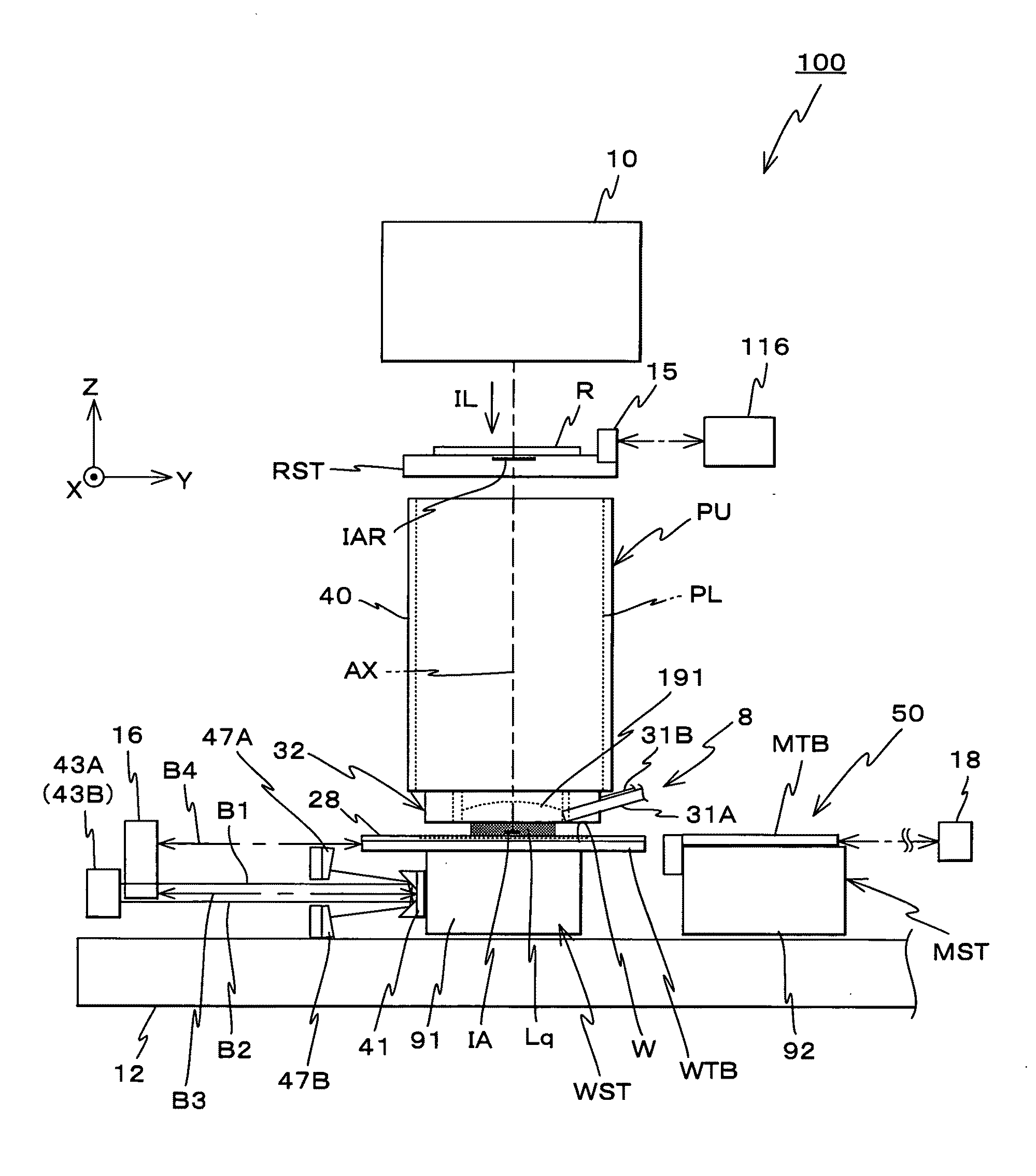
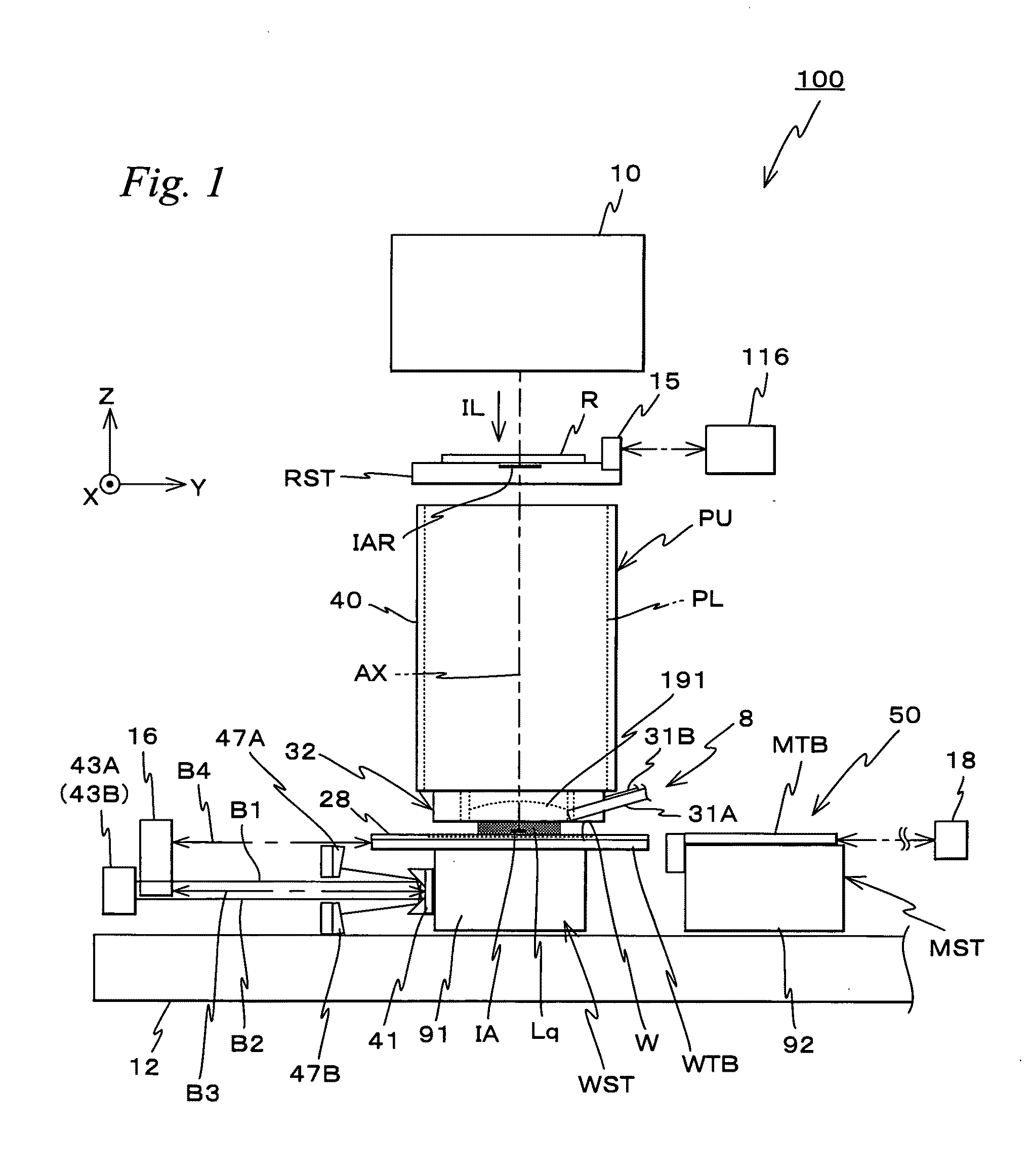
[0054]FIG. 1 shows a schematic configuration of an exposure apparatus 100 in the embodiment. Exposure apparatus 100 is a projection exposure apparatus of the step-and-scan method, namely the so-called scanner. As it will be described later, a projection optical system PL is arranged in the embodiment, and in the description below, a direction parallel to an optical axis AX of projection optical system PL will be described as the Z-axis direction, a direction within a plane orthogonal to the Z-axis direction in which a reticle and a wafer are relatively scanned will be described as the Y-axis direction, a direction orthogonal to the Z-axis and the Y-axis will be described as the X-axis direction, and rotational (inclination) directions around the X-axis, the Y-axis, and the Z-axis will be described as θx, θy, and θz directions, respectively.

[0055]Exposure apparatus 100 is equipped ...


PUM


Abstract

A first positional information of a wafer stage is measured using an interferometer system such as, for example, a Z interferometer. At the same time, a second positional information of the wafer stage is measured using a surface position measurement system such as, for example, two Z heads. Moving average is applied to a difference between the first positional information and the second positional information for a predetermined measurement time to set a coordinate offset, and the coordinate offset is used to inspect the reliability of output signals of the surface position measurement system. When the output signals are confirmed to be normal, servo control of the wafer stage is performed using a sum of the first positional information and the coordinate offset. According to the servo control by this hybrid method, drive control of the wafer stage which has the stability of the interferometer and the precision of the Z heads becomes possible.

Description

CROSS-REFERENCE TO RELATED APPLICATIONS[0001]This non-provisional application claims the benefit of Provisional Application No. 60 / 960,157 filed Sep. 18, 2007, the disclosure of which is hereby incorporated herein by reference in its entirety.BACKGROUND OF THE INVENTION[0002]1. Field of the Invention[0003]The present invention relates to movable body drive methods and movable body drive systems, and pattern formation methods and pattern formation apparatuses, and more particularly, to a movable body drive method and a movable body drive system that drives a movable body substantially along a two-dimensional plane, and a pattern formation method using the movable body drive method and a pattern formation apparatus equipped with the movable body drive system.[0004]2. Description of the Background Art[0005]Conventionally, in a lithography process for manufacturing electron devices (microdevices) such as semiconductor devices (such as integrated circuits) and liquid crystal display devi...

Claims


Application Information

Patent Timeline
IPC IPC(8): G03B27/42G01B11/02
CPCG03F7/70725G03F7/70775G03F9/7088G03F9/7011G03F9/7019G03F7/7085G03F7/70758
Inventor KANAYA, YUHO
Owner NIKON CORP
Features
  • Generate Ideas
  • Intellectual Property
  • Life Sciences
  • Materials
  • Tech Scout
  • Unparalleled Data Quality
  • Higher Quality Content
  • 60% Fewer Hallucinations
Learn More