High frequency acousto-optic frequency shifter having wide acceptance angle

Active Publication Date: 2009-03-19
GOOCH & HOUSEGO
View PDF3 Cites 4 Cited by
  • Summary
  • Abstract
  • Description
  • Claims
  • Application Information

AI Technical Summary

Benefits of technology

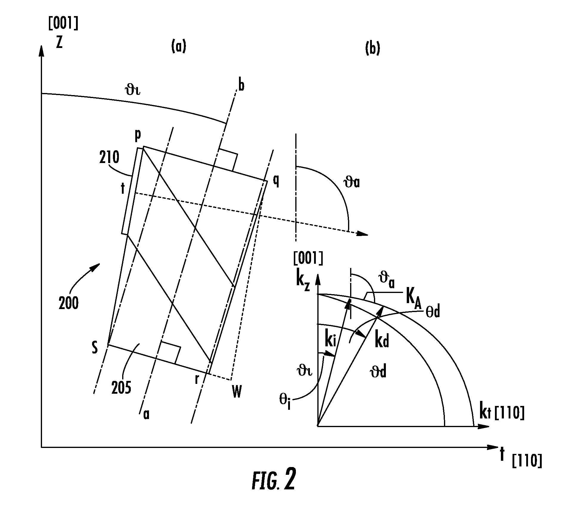
[0013]Embodiments of the present invention utilizes the dual-polarization/parallel-tangents solution in slow-shear acoustic-mode, wherein both o-ray & e-ray polarized beams are simultaneously diffracted at the same drive frequency and input angle. In one embodiment, −73<θa<−70 degrees and 52<θi<56 degrees, such as −71.4<θa<−71.2 degrees, and 54<θi<56 degrees in another embodiment. Specifically, proper selection of θi and θa for a given acoustical drive frequency has been found to have the beneficial property that two diffracted beams (the +1 and the −1 orders) can be simultaneously produced from a single input beam at exac

Problems solved by technology

If this condition is not met, then significant ambiguity regarding the velocity of the remote surface will be introduced, and the signal processing will not be able to correct the situation, giving rise to erroneous results.
Because the frequency shifting process is not 100% efficient, a small amount of the residual incident beam (unshifted “zero degree” beam) also exits the Bragg cell device through the second (output) aperture.
There are well known problems relating to producing a large frequency shift (e.g. >100 MHz) using a conventional AOM.
The angular tolerance with which the laser beam may deviate from this condition in the standard (40 or 80 MHz) devices is small if they are to continue working efficiently, generally of the order of tens of milli-radians, and this makes alignment difficult.
This means that any divergence or beam misalignment in excess of this value will cause a noticeable drop in efficiency of the device.
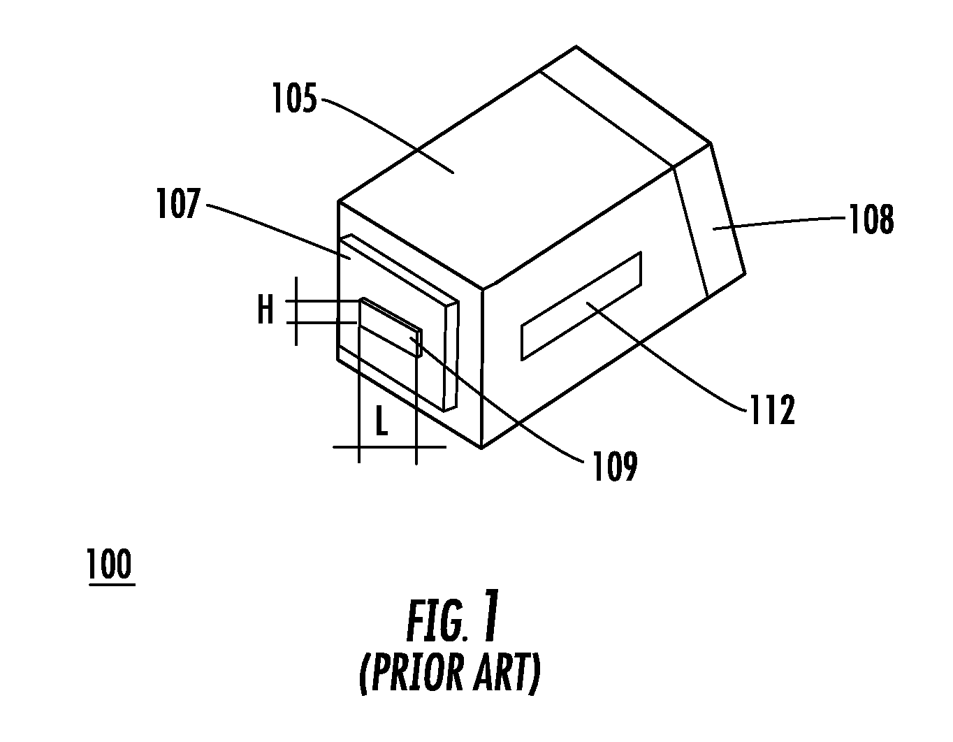
However, if the transducer L is shortened (e.g. make L<10 mm) in an attempt to increase the angular acceptance given by equation (1), another problem arises, specifically, the inability to maintain diffraction efficiency at the previous value.
However, more RF power will be needed to drive the shorter device in order to maintain a given level of efficiency, also it is possible that the aco

Method used


Image

  • High frequency acousto-optic frequency shifter having wide acceptance angle
  • High frequency acousto-optic frequency shifter having wide acceptance angle
  • High frequency acousto-optic frequency shifter having wide acceptance angle

Examples


Example

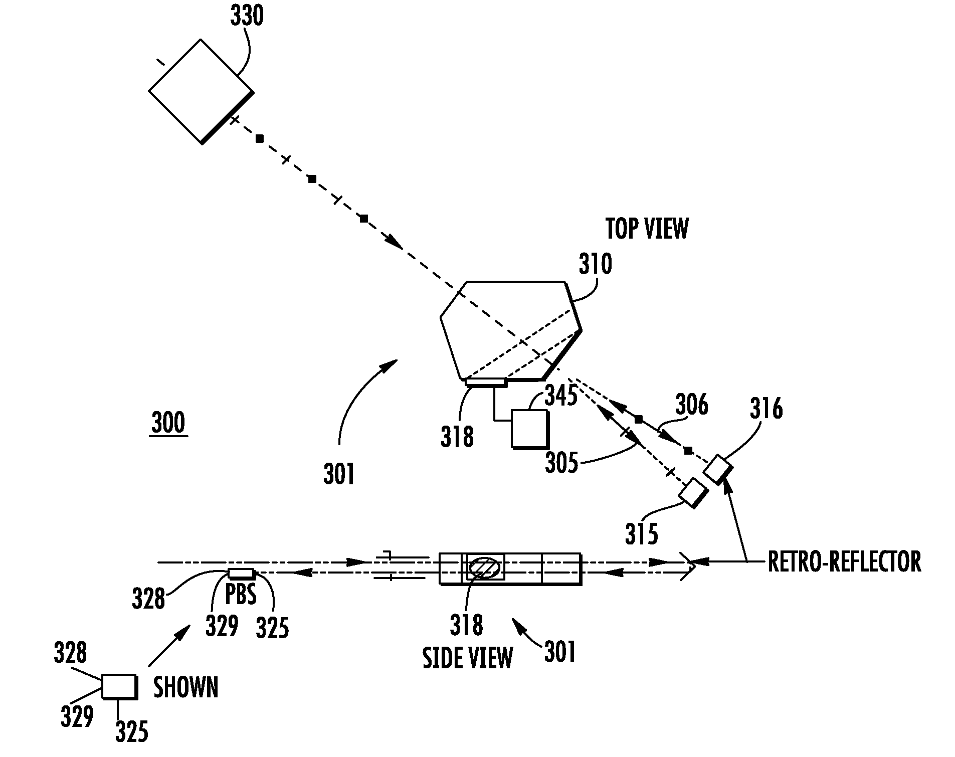
[0035]Embodiments of devices according to the invention described herein are acousto-optic (AO) frequency shifters capable of providing shifts in the hundreds of MHz for a single optical beam. Using double-passing, such as provided by utilizing a retroreflector, frequency shifts of over 1 GHz can be obtained. Embodiments of the present invention use an AO interaction in an anisotropic (birefringent) crystal which has previously only been applied in the context of AOTFs.

[0036]In a conventional AOTF, it is customary to use an anisotropic acousto-interaction in which the input state of polarization (assumed linear) is “flipped” to the orthogonal state in the process. The function of the conventional AOTF device is to realize the desired electronically programmable optical filter which can be tuned rapidly over a wide range of center wavelengths, possibly an octave or more. This tuning aspect requires a broadband transducer and a complex electrical matching network. In such a convention...


PUM


Abstract

An acousto-optic (AO) frequency shifter includes an anisotropic crystal having an optical axis and an input face, and an acoustic transducer having electrodes affixed to the face for receiving an electrical signal and projecting an acoustic wave into the crystal. The anisotropic crystal is cut relative to the face so that the transducer is at an acoustic angle (θa) corresponding to a predetermined angle of incidence (θi) of an optical beam to be directed relative to the optic axis of the anisotropic crystal to substantially satisfy the parallel tangents phase matching condition.

Description

FIELD OF THE INVENTION[0001]The present invention relates to acousto-optic frequency shifters, which are also sometimes referred to as frequency translators.BACKGROUND OF THE INVENTION[0002]Lasers are used in a wide variety of optical sensors. The natural frequency of a laser depends on the lasing medium and the cavity optics. However, once these parameters are chosen, the emission frequency is fixed and frequency stability of the laser beam is generally very good. Thus, in a conventional Helium-Neon laser a common wavelength of operation is 632.8 nm, corresponding to a frequency of 4.7408×10¹⁴ Hz. In a typical application, a pair of beams is derived from a single laser (for example using a beam-splitter), and the frequency of one of these beams is shifted by a fixed amount, such as in the tens or hundreds of MHz, as an aid to signal processing in an optical sensor-based system.[0003]In a typical optical sensor-based system, such as a laser velocimeter or laser vibrometer, one of th...

Claims


Application Information

Patent Timeline
IPC IPC(8): G02F1/33
CPCG02F1/11G02F1/353G02F2201/17G02F2001/3542G02F1/3544G02F1/3542
Inventor PANNELL, CHRISTOPHER N.WARD, JONATHAN DAVID
Owner GOOCH & HOUSEGO
Why Eureka
Try Eureka