Fiber bragg grating for high temperature sensing

a technology of fiber bragg grating and temperature sensing, which is applied in the direction of heat measurement, instruments, manufacturing tools, etc., can solve the problems of undesirable thermal instability of ultraviolet light-induced fbg sensors, and achieve the effects of enhancing photosensitivity, enhancing an amorphous network crosslink mean coordination number, and enhancing photosensitivity

Active Publication Date: 2009-03-19
AIR PROD & CHEM INC
View PDF12 Cites 19 Cited by
  • Summary
  • Abstract
  • Description
  • Claims
  • Application Information

AI Technical Summary

Benefits of technology

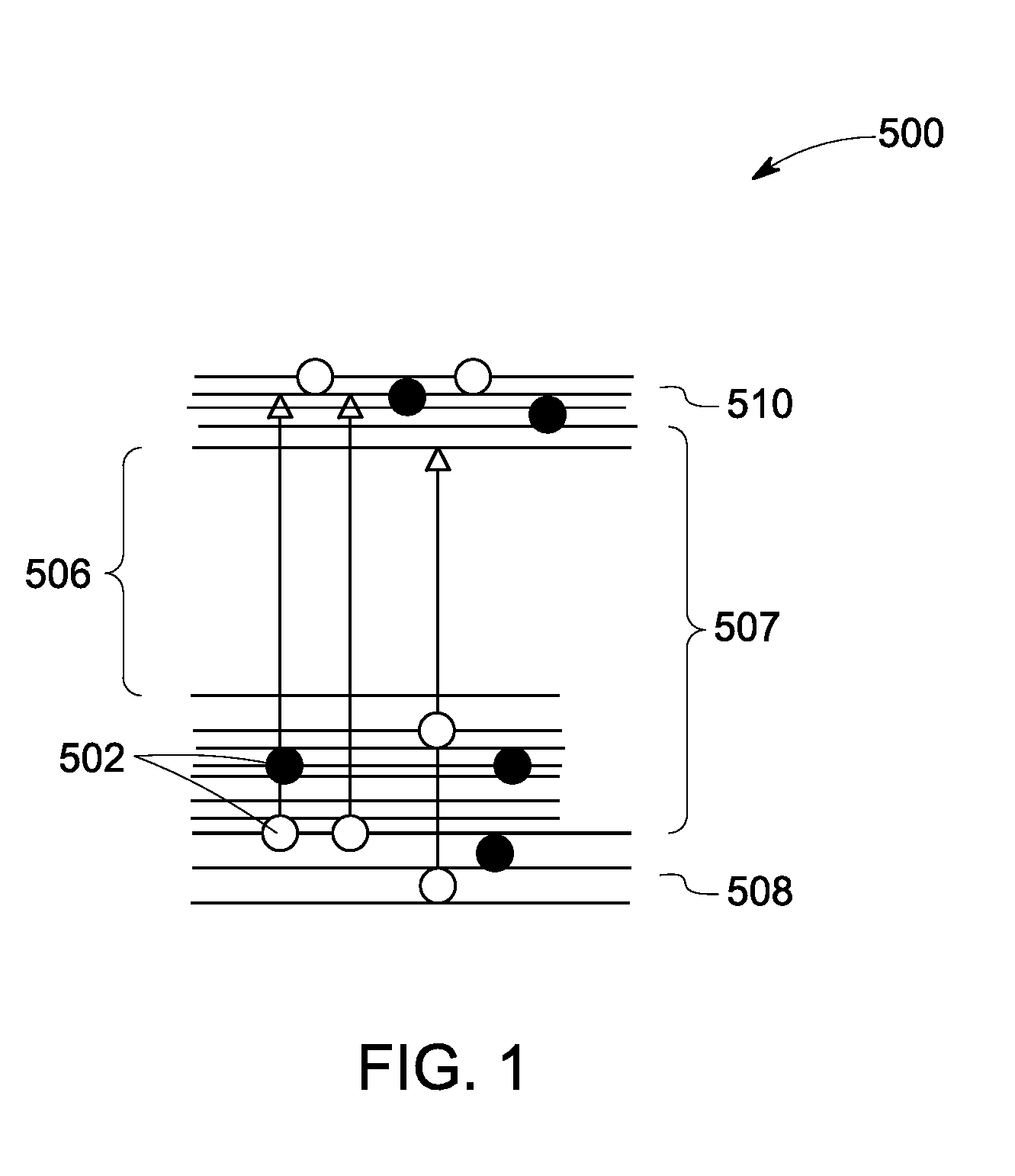
[0006]In accordance with one aspect of the invention, a method of fiber core material band-gap engineering for artificially fiber material properties is provided. The method includes doping the fiber core material with one or more atoms for enhancing photosensitivity to the fiber material. The method also includes co-doping the fiber core material with one or more ions for enhancing an amorphous network crosslink mean coordination number. The method further includes thermally annealing the fiber core material for widening the band gap of the fiber core material.
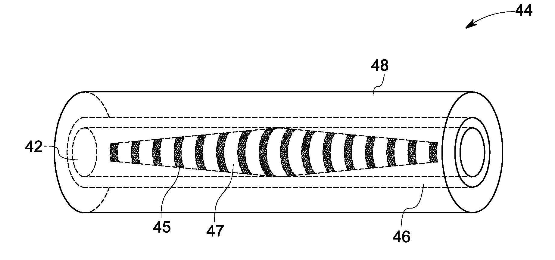
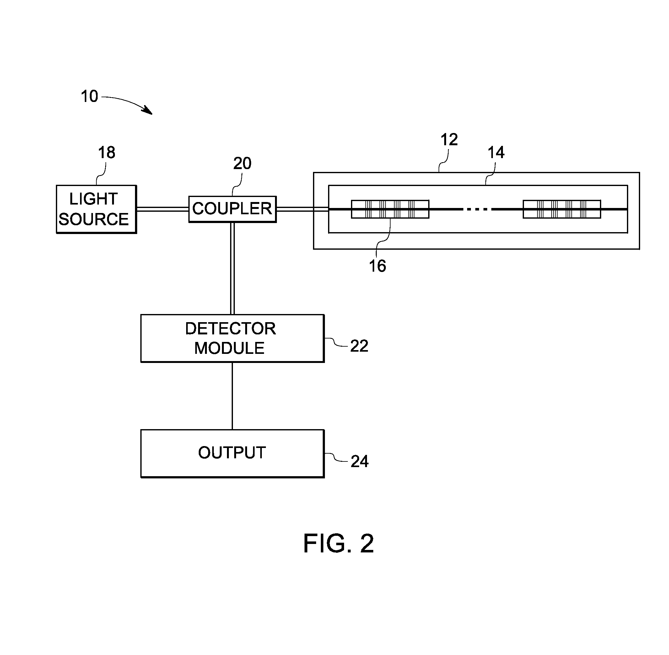
[0007]In accordance with one aspect of the invention, a method of fabrication of a thermally stabilized fiber Bragg grating based temperature sensing device is provided. The method includes doping a fiber core material for enhancing photosensitivity. The method also includes co-doping the fiber core material for increasing a mean coordination number The method further includes inscribing a periodic or quasiperiodic modulated refractive index structure in the fiber core as a Type-I-like grating. The method also includes performing a band-gap engineering of the Type-I-like grating to prompt a growth of a Type IIA-like grating. The method also includes structural processing of the Type-II-like grating and annealing to form a nanophase tetrahedral Type II-like grating structure.

Problems solved by technology

However, the ultraviolet (UV) light induced FBG sensors exhibit undesirable thermal instability at elevated temperatures.
A Type-II grating inscribed after a Type-IIA grating has a broad reflective spectrum that is undesirable for high temperature sensing applications.

Method used


Image

  • Fiber bragg grating for high temperature sensing
  • Fiber bragg grating for high temperature sensing
  • Fiber bragg grating for high temperature sensing

Examples


examples

[0053]The examples that follow are merely illustrative, and should not be construed to be any sort of limitation on the scope of the claimed invention.

[0054]FIG. 10 is a graphical comparison 80 between an exemplary reflection spectrum 82 obtained from a thermal stabilized nanocrystalline fiber Bragg grating (NFBG) sensor, fabricated with above processes, and a reflection spectrum 84 obtained from a its initial Type-I-like grating. In the illustrated embodiment, the X axis 86 represents wavelength measured in nanometers and the Y-axis 88 represents a reflected power loss measured in decibels (dB). A peak reflected power loss represented by reference numeral 90 corresponds to a fiber core guided mode of the fiber optic sensor 30, while a peak referenced by numeral 92 represents a fiber core guided mode of the commercial Fiber Bragg grating based sensor. As illustrated, a wavelength shift of about 2.87 nm occurs between the peaks 90 and 92. Further, the power loss in the fiber optic se...


PUM

PropertyMeasurementUnit
temperatureaaaaaaaaaa
temperaturesaaaaaaaaaa

Abstract

A method of fiber core material band gap engineering for artificially modifying fiber material properties is provided. The method includes doping the fiber core material with one or more atoms for enhancing photosensitivity to the fiber material. The method also includes co-doping the fiber core material with one or more ions for enhancing an amorphous network crosslink mean coordination number. The method further includes thermally annealing the fiber core material for widening the band gap of the fiber core material.

Description

BACKGROUND[0001]The invention relates generally to a fiber Bragg grating based temperature sensing device and, more particularly, to thermally stabilized fiber Bragg grating based temperature sensing devices that can be operated at elevated temperatures beyond 1000 K.[0002]Temperature sensing is essential for a safe and efficient operation and control of many industrial processes. Industrial processes such as coal boiler operation, combustion, power generation, and gasification involve the measurement of high temperatures either for real-time industrial processmonitoring or for control and optimization.[0003]In general, there are several techniques used for measurement of temperatures beyond 1000 K. Some of the commonly used techniques include a thermocouple, pyrometry and blackbody measurement. Further, Fiber Bragg grating (FBG) based fiberoptic temperature sensors have been found to be a potential method for elevated temperature measurement. FBG is a high quality reflector constru...

Claims


Application Information

Patent Timeline
Patent Type & Authority Applications(United States)
IPC IPC(8): G02B6/00
CPCG01K11/3206G02B6/02204G02B6/02138G02B6/02114
Inventor XIA, HUAMCCARTHY, KEVIN THOMASDENG, KUNG-LI JUSTINLOPEZ, FULTON JOSEAVAGLIANO, AARON JOHN
Owner AIR PROD & CHEM INC
Why Eureka
Try Eureka