Integrated Half-Bridge Power Circuit

a power circuit and half-bridge technology, applied in the direction of electric variable regulation, process and machine control, instruments, etc., can solve the problems of cf and sf's ability to meet these demands without affecting the other side, and achieve the effect of reducing parasitics, reducing parasitics, and improving resistance and gate-to-drain charg

Inactive Publication Date: 2009-03-26
NXP BV
View PDF19 Cites 5 Cited by
  • Summary
  • Abstract
  • Description
  • Claims
  • Application Information

AI Technical Summary

Benefits of technology

[0006]As will become clearer as the present description continues, the on-resistance and the gate-to-drain charge are improved via exemplary embodiments described herein. Other be

Problems solved by technology

For example, as the demand for faster switching frequencies increases, parasitic effects in su

Method used


Image

  • Integrated Half-Bridge Power Circuit
  • Integrated Half-Bridge Power Circuit
  • Integrated Half-Bridge Power Circuit

Examples


Embodiment Construction

[0014]In the following detailed description, for purposes of explanation and not limitation, exemplary embodiments disclosing specific details are set forth in order to provide a thorough understanding of the present invention. However, it will be apparent to one having ordinary skill in the art having had the benefit of the present disclosure, that the present invention may be practiced in other embodiments that depart from the specific details disclosed herein. Moreover, descriptions of well-known devices, methods and materials may be omitted so as to not obscure the description of the present invention.

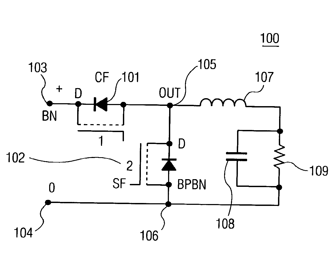
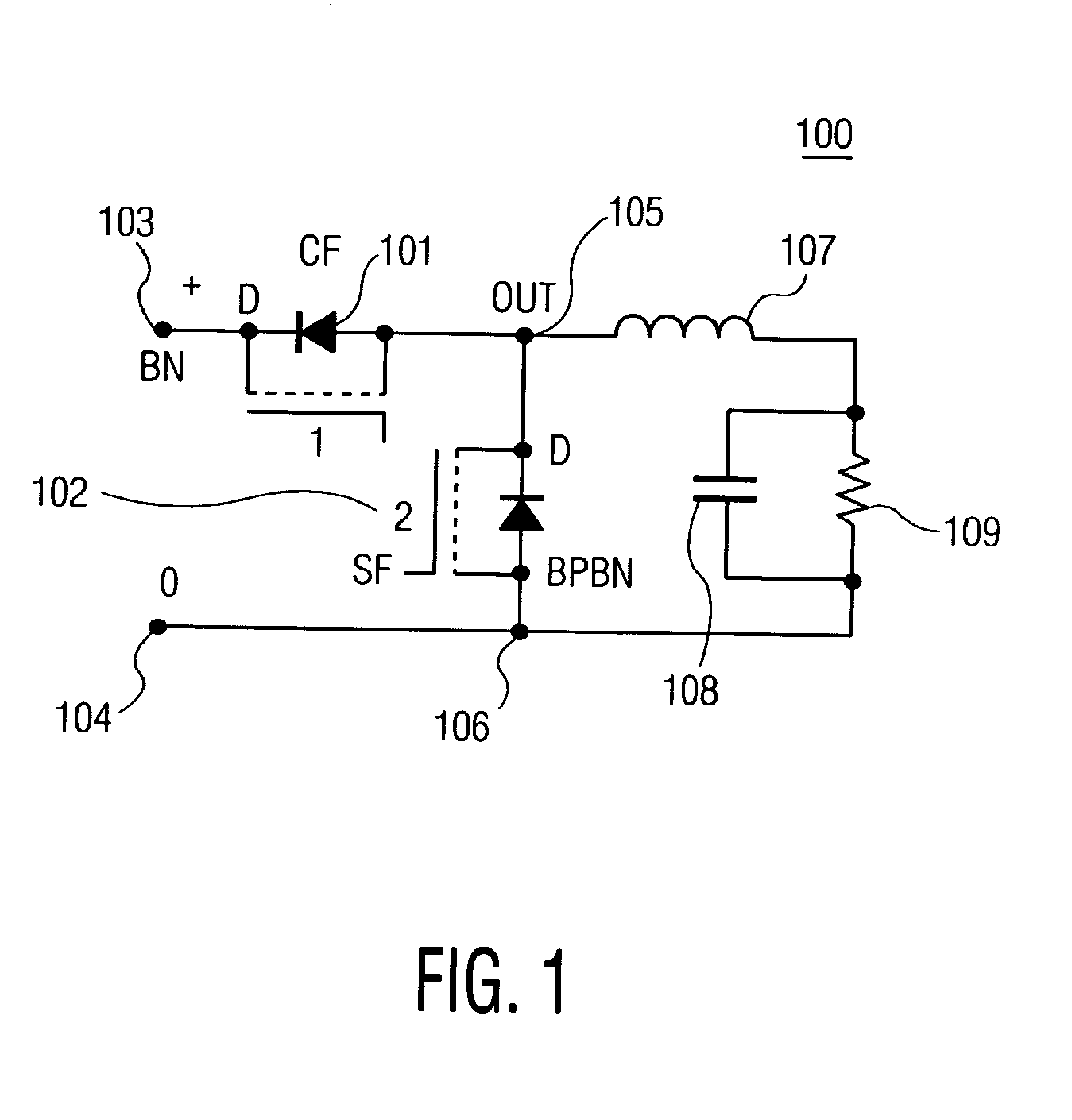
[0015]FIG. 1 shows a down converter circuit 100 in accordance with an exemplary embodiment of the present invention. The circuit 100 is illustratively a Buck-converter circuit with a CF 101 and an SF 102. The input voltage, which is illustratively on the order of approximately 12V, is from a voltage source or power supply (not shown), and is applied over input terminals 103 and 104...


PUM

PropertyMeasurementUnit
Electrical conductivityaaaaaaaaaa
Electrical conductoraaaaaaaaaa
Semiconductor propertiesaaaaaaaaaa

Abstract

A down converter includes an integrated circuit, which includes a control FET (CF) and a synchronous rectifier FET (SF). The control FET is a lateral double-diffused (LDMOS) FET, and the conductivity-type of the LDMOS FET and the conductivity-type of the substrate are of the same type.

Description

BACKGROUND OF THE INVENTIONField of the Invention[0001]The present invention relates generally to integrated power conversion circuits using a half bridge, and particularly, to integrated power-transistors for a down-converter power supply having improved switching characteristics.SUMMARY OF THE INVENTION[0002]Power-converters are often used in power supplies, power amplifiers and motor drives. Down converters, including Buck converters are often used to convert an input voltage to a lower voltage for supplying power to a load, such as a microprocessor. These microprocessors have applicability in personal computers (PC) as well as other electronic devices. In PC applications, the input voltage to the converter is on the order of 12 V, and the required output is on the order of approximately 1.4 V, or a factor of about ten in step-down. Moreover, the required output currents of these converters are increasing to above 50 A, further adding to the design considerations of these circuit...

Claims


Application Information

Patent Timeline
IPC IPC(8): H02B1/24H01L27/085H01L27/088H02M3/158
CPCH01L27/0629H01L27/088Y02B70/1466H02M3/1588H01L27/0922Y02B70/10H01L29/7816
Inventor LUDIKHUIZE, ADRIANUS WILLEMVAN DER POL, JACOB ANTONIUSGROVER, RAYMOND J.
Owner NXP BV
Why Eureka
Try Eureka