

OLED display encapsulation with the optical property
Inactive Publication Date: 2009-03-26
EASTMAN KODAK CO
View PDF26 Cites 39 Cited by
- Summary
- Abstract
- Description
- Claims
- Application Information
AI Technical Summary
Benefits of technology
[0047]The invention and its objects and advantages will become more apparent in the detailed description of the preferred embodiment presented below.
Problems solved by technology
However, the materials comprising the organic EL element are sensitive and, in particular, are easily destroyed by moisture and high temperatures (for example greater than 140 degrees C.).
In contrast, typically polymeric materials have a moisture permeation rate of approximately 0.1 gm / m2 / day and cannot adequately protect the OLED materials without additional moisture blocking layers.
However, such protective layers also cause additional problems with light trapping in the layers since they may be of lower index than the light-emitting organic layers.
While multiple layers provide better protection for OLED displays, thicker layers diminish transparency and as a result brightness and color saturation of the display.
In practice, in any system it is difficult to avoid some direct reaction of the different precursors leading to a small amount of chemical vapor deposition reaction.
Self-saturating surface reactions make ALD relatively insensitive to transport non-uniformities, which might otherwise impair surface uniformity, due to engineering tolerances and the limitations of the flow system or related to surface topography (that is, deposition into three dimensional, high aspect ratio structures).
As a general rule, a non-uniform flux of chemicals in a reactive process generally results in different completion times over different portions of the surface area.
However, in spite of its inherent technical capabilities and advantages, a number of technical hurdles still remain.
However, it is difficult to obtain a reliable scheme for introducing the needed series of gaseous formulations into a chamber at the needed speeds and without some unwanted mixing.
In a typical ALD chamber the volume (V) and pressure (P) are dictated independently by the mechanical and pumping constraints, leading to difficulty in precisely controlling the residence time to low values.
Existing ALD approaches have been compromised with the trade-off between the need to shorten reaction times with improved chemical utilization efficiency, and, on the other hand, the need to minimize purge-gas residence and chemical removal times. One approach to overcome the inherent limitations of “pulsed” delivery of gaseous material is to provide each reactant gas continuously and to move the substrate through each gas in succession.
While systems such as those described in the '563 Yudovsky and '022 Suntola et al. disclosures may avoid some of the difficulties inherent to pulsed gas approaches, these systems have other drawbacks.
The complex arrangements of both the gas flow delivery unit of the '563 Yudovsky disclosure and the gas flow array of the '022 Suntola et al. disclosure, each providing both gas flow and vacuum, make these solutions difficult to implement and costly to scale and limit their potential usability to deposition applications onto a moving substrate of limited dimensions.
Moreover, it would be very difficult to maintain a uniform vacuum at different points in an array and to maintain synchronous gas flow and vacuum at complementary pressures, thus compromising the uniformity of gas flux that is provided to the substrate surface.
Method used
View moreImage
Smart ImageViewing Examples

Examples
example 1
[0163]An interference filter was created by depositing layers of zinc oxide and alumina interchangeably on a 62×62×1 mm glass slide using ALD system. The aim thicknesses of the layers were in order from the substrate up:
Zinc oxide100 nmAlumina100 nmZinc oxide100 nmAlumina100 nmZinc oxide100 nmAlumina200 nmZinc oxide100 nmAlumina100 nmZinc oxide100 nmAlumina100 nmZinc oxide100 nm
[0164]The diagram of the filter layers is shown in FIG. 22a. The absorbance of the filter was measured showing the peaks near 570 nm and around 700 nm which is shown in FIG. 22b.
Login to View More PUM
| Property | Measurement | Unit |
|---|---|---|
| Temperature | aaaaa | aaaaa |
| Nanoscale particle size | aaaaa | aaaaa |
| Nanoscale particle size | aaaaa | aaaaa |
Abstract
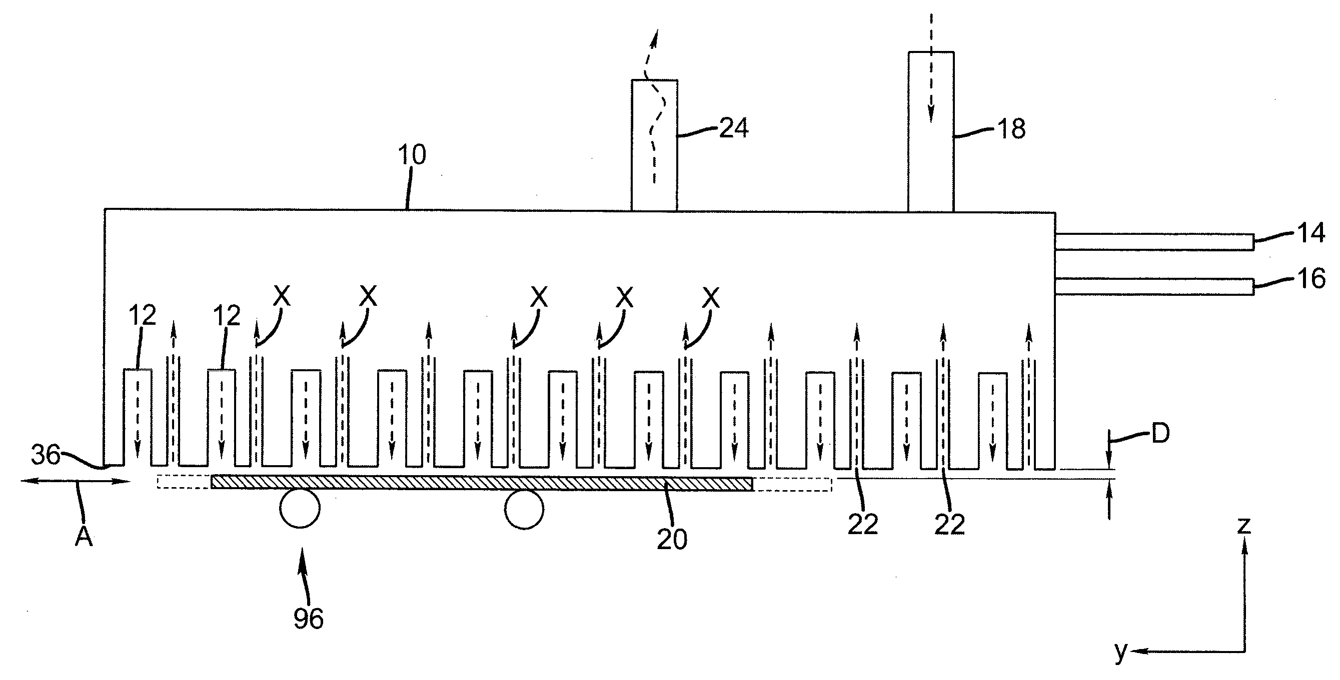
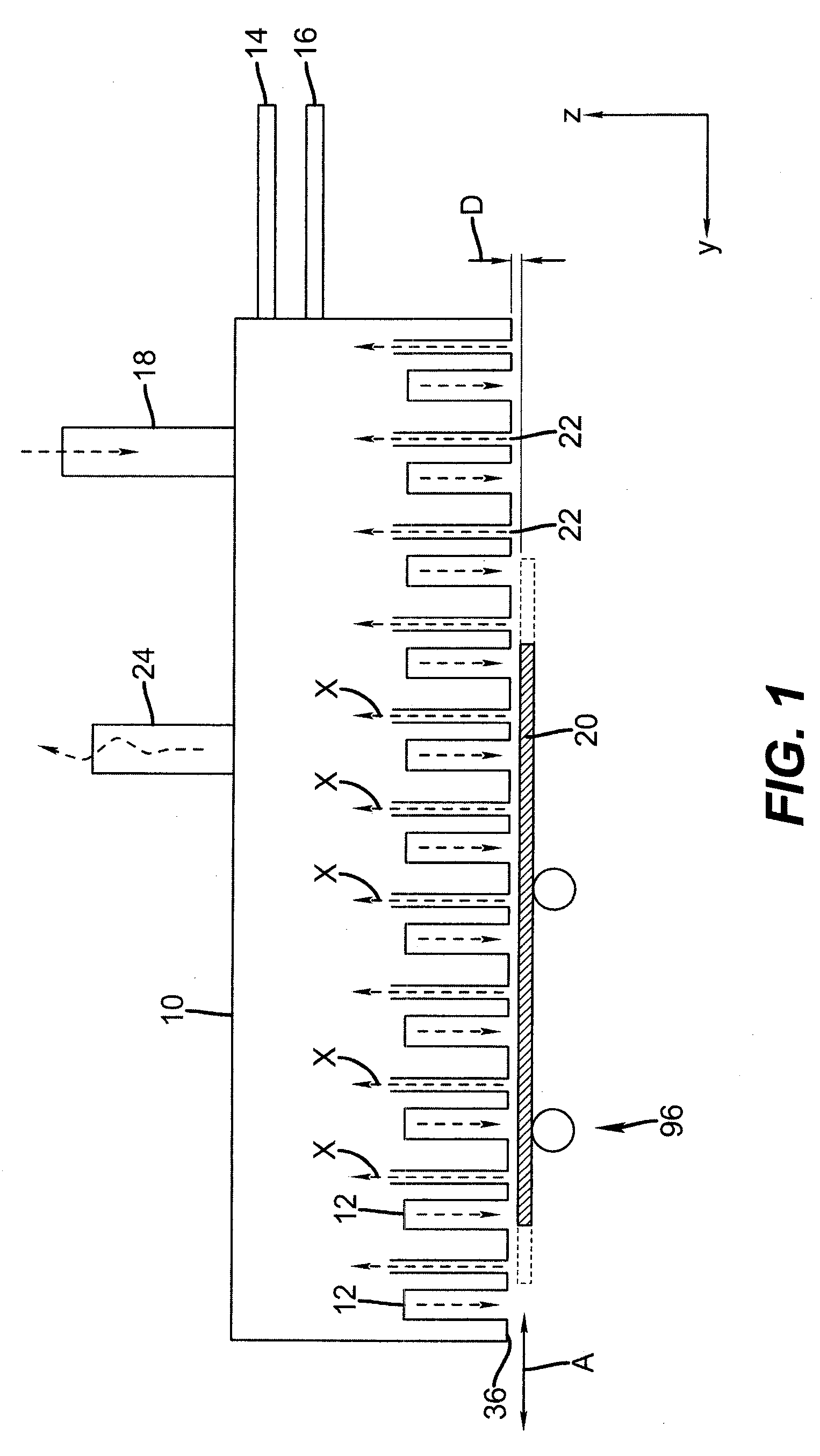
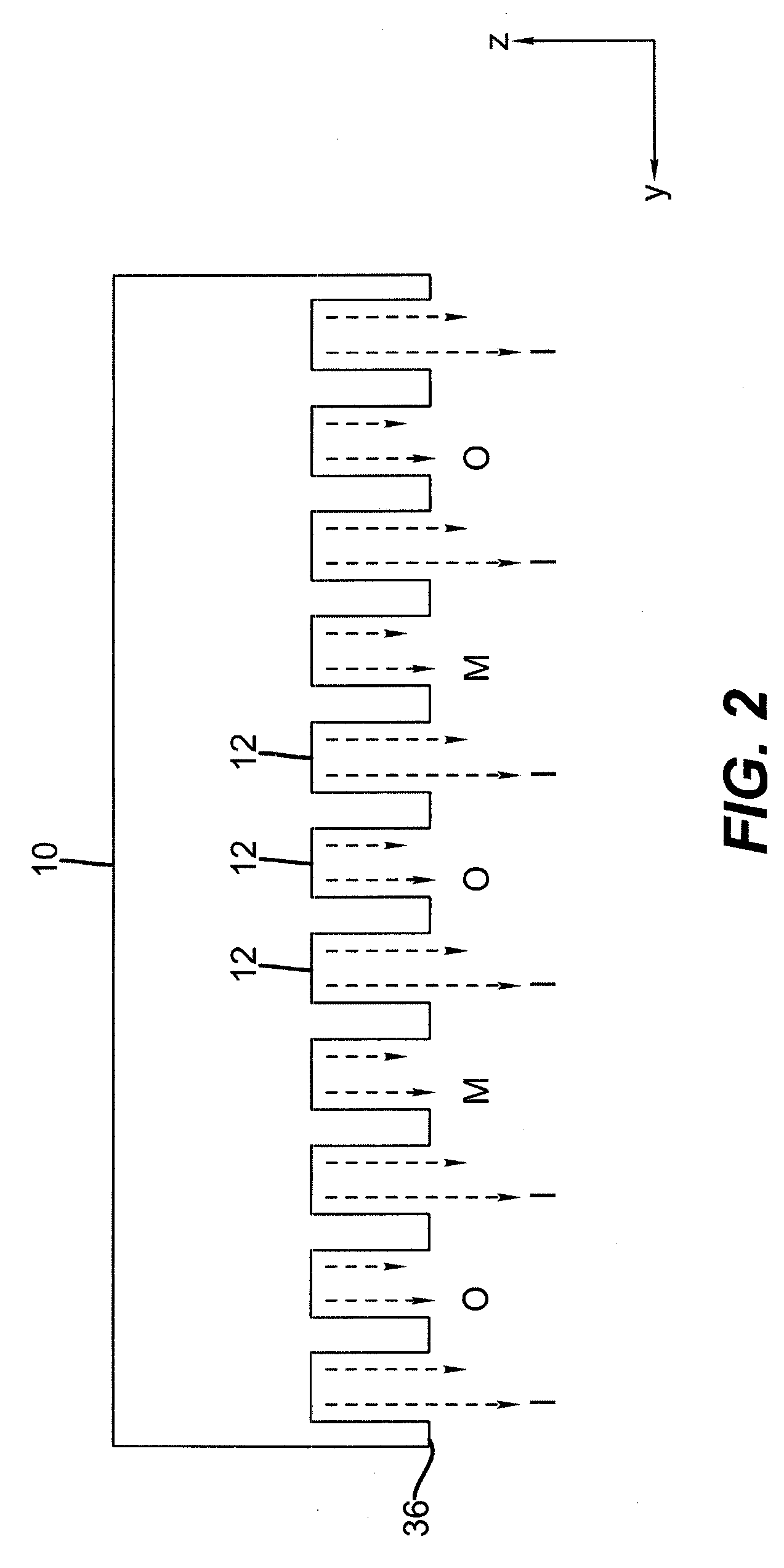
A process of making an optical film or optical array comprises: a) simultaneously directing a series of gas flows along elongated substantially parallel channels to form a first thin film on a substrate; wherein the series of gas flows comprises, in order, at least a first reactive gaseous material, an inert purge gas, and a second reactive gaseous material; wherein the first reactive gaseous material is capable of reacting with a substrate surface treated with the second reactive gaseous material to form the first thin film; b) repeating step a) a plurality of times to produce a first thickness of a first film layer with a first optical property; wherein the process is carried out at or above atmospheric pressure; c) repeating steps a) and b) to produce a second film layer; and wherein the process is carried out substantially at or above atmospheric pressure.
Description
CROSS REFERENCE TO RELATED APPLICATIONS[0001]Reference is made to commonly-assigned copending U.S. patent application Ser. No. 11 / 392,007, filed Mar. 29, 2006, by David Levy, entitled PROCESS FOR ATOMIC LAYER DEPOSITION; U.S. patent application Ser. No. 11 / 392,006, filed Mar. 29, 2006, by David Levy, entitled APPARATUS FOR ATOMIC LAYER DEPOSITION; U.S. patent application Ser. No. 11 / 620,744, by David Levy, entitled DEPOSITION SYSTEM AND METHOD USING A DELIVERY HEAD SEPARATED FROM A SUBSTRATE BY GAS PRESSURE; and U.S. patent application Ser. No. 11 / 620,740, by Nelson et al. entitled DELIVERY DEVICE COMPRISING GAS DIFFUSER FOR THIN FILM DEPOSITION; the disclosures of which are incorporated herein.FIELD OF THE INVENTION[0002]This invention generally relates to thin film devices and components, such as electronic light emitting displays, sensor arrays, and other electronic devices, environmental barrier layers, optical thin film layers, where thin-film layers are made by vapor depositio...
Claims
Login to View More Application Information
Patent Timeline
 IPC IPC(8): G02B5/30
CPCC23C16/45529C23C16/45551H01L51/56H01L51/5237H01L51/5262H01L27/322H10K59/38H10K50/844H10K50/85H10K71/00
InventorFEDOROVSKAYA, ELENA A.FYSON, JOHN R.AGOSTINELLI, JOHN A.COK, RONALD S.
OwnerEASTMAN KODAK CO