Biological specimen imaging method and biological specimen imaging apparatus

a biological specimen and imaging method technology, applied in the field of analyzing methods and analyzing apparatuses, can solve the problems of difficult to bring a lens into focus on the specific region of the specimen with naked eyes, the emission of luminescent specimens is extremely feeble, and the inability to directly confirm the luminescence of biological specimens in most cases

Inactive Publication Date: 2009-04-02
OLYMPUS CORP
View PDF6 Cites 144 Cited by
  • Summary
  • Abstract
  • Description
  • Claims
  • Application Information

AI Technical Summary

Problems solved by technology

However, since an intensity of light of self-luminescence from a biological specimen is generally extremely feebler the luminescence from the biological specimen cannot directly be confirmed with naked eyes in most cases.
Even when an optical element (e.g., detection lens, etc.) is adjusted to a specimen emitting a feeble light, it is naturally difficult to bring a l

Method used


Image

  • Biological specimen imaging method and biological specimen imaging apparatus
  • Biological specimen imaging method and biological specimen imaging apparatus
  • Biological specimen imaging method and biological specimen imaging apparatus

Examples


third embodiment

1. Basic Principle of Invention

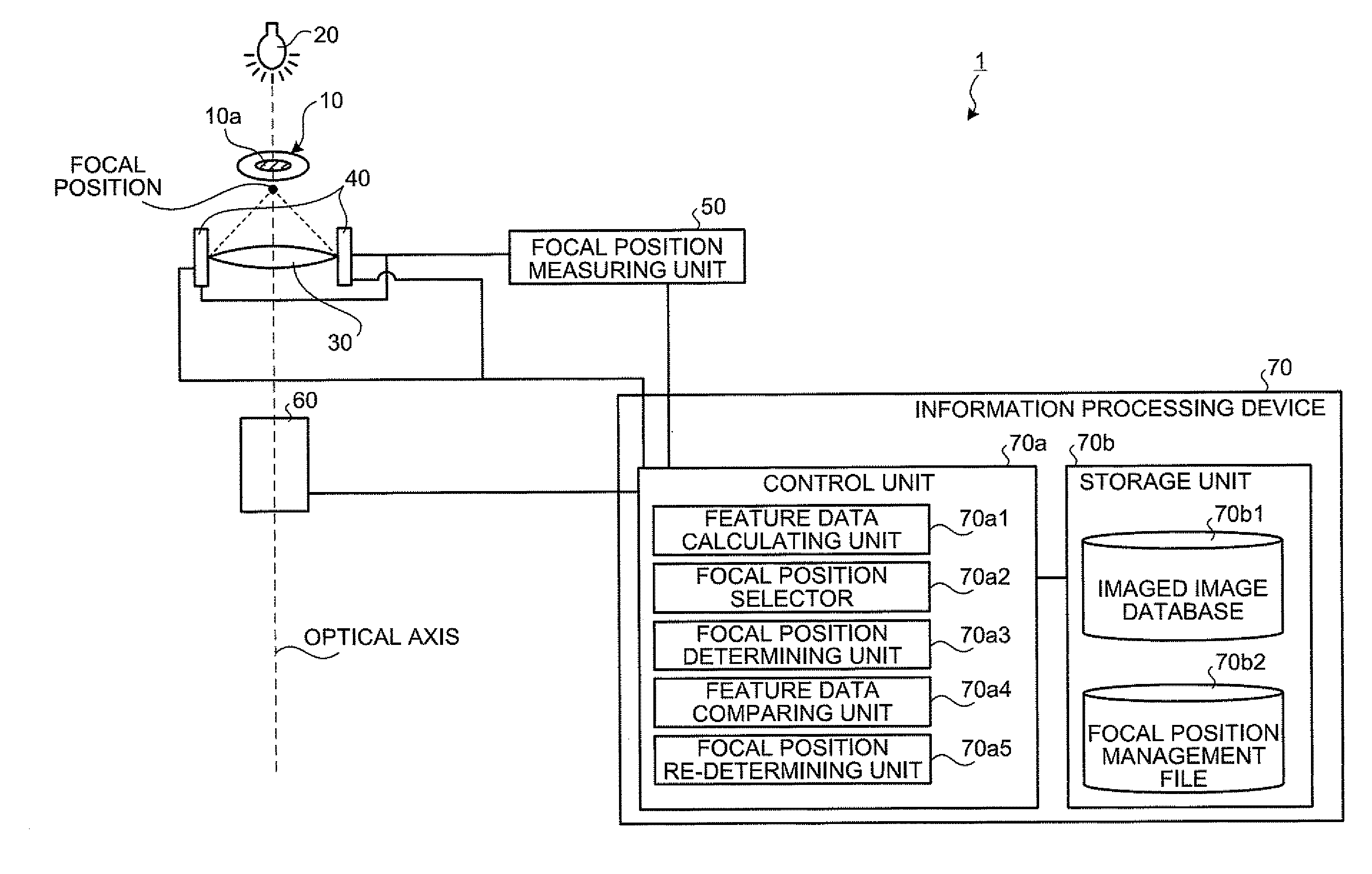
[0193]Firstly, a basic principle of the biological specimen imaging method and the biological specimen imaging apparatus according to the present invention will be explained in detail. The present invention images a biological specimen, which is stored in a storing section of a substrate having plural storing sections and emits a feeble light, through an objective lens. In the present invention, any one of the substrate and objective lens or both is moved until the desired storing section falls within the field of view of the objective lens, any one of the focal position of the objective lens at the near point and the focal position of the objective lens at the far point or both is measured, the focal position of the objective lens, which is focused on an observed target region in the biological specimen stored in the desired storing section is determined based on the measured focal position, the focal position of the objective lens is adjusted to the ...

example

[0242]In the present example, the objective lens was focused on plural HeLa cells in which plasmid vector was transduced, the HeLa cell, which was the subject, was selected from the plural HeLa cells, and the luminescent amount and ATP amount from mitochondria in the selected HeLa cell were measured over time, by using the focal position determining apparatus 1 according to the second embodiment. The experiment in the present example was performed according to the (step 1) to (step 7) described below.

[0243](Step 1) A fusion gene in which fluorescent protein (GFP), mitochondria localization signal, and luciferase were combined was prepared.

[0244](Step 2) A plasmid vector having the fusion gene therein was transduced to a HeLa cell.

[0245](Step 3) With the use of the focal position determining apparatus 1, the focal position of the objective lens was adjusted to the mitochondria in the HeLa cell, and the HeLa cell was imaged by the CCD camera with the illumination and without the illum...

first embodiment

[0282]The configuration of an apparatus for executing a luminescent specimen imaging method according to the first embodiment will be explained with reference to FIG. 26. FIG. 26 is a view for showing one example of a configuration of an apparatus for executing a luminescent specimen imaging method according to the first embodiment. As shown in FIG. 26, the apparatus for executing the luminescent specimen imaging method according to the first embodiment images a specimen 1A, which is a subject to be imaged, in a short exposure time or on a real time. It is composed of an objective lens 2A, the condenser lens 3A, CCD camera 4A and CPU 5A. The apparatus may include a zoom lens 6A as illustrated.

[0283]The specimen 1A is a luminescent specimen. For example, the specimen 1A is a luminescent protein (e.g., luminescent protein expressed from a transduced gene (luciferase gene, etc.)), luminescent cell, luminescent cell population, luminescent tissue specimen, luminescent organ, luminescent...


PUM


Abstract

In a biological specimen imaging method, a biological specimen which is stored in a storing section of a substrate having plural storing sections and emitting a feeble light is imaged through an objective lens. The biological specimen imaging method includes moving any one of the substrate and the objective lens or both until the desired storing section falls within the field of view of the objective lens, measuring any one of a focal position at a near point and the focal position at a far point of the objective lens or both, determining the focal position of the objective lens focused on an observed target region in the biological specimen stored in the desired storing section based on the measured focal position, and adjusting the focal position of the objective lens to the determined focal position so as to image the biological specimen through the objective lens.

Description

CROSS-REFERENCE TO RELATED APPLICATIONS[0001]This application is a continuation of PCT international application Ser. No. PCT / JP2007 / 61139 filed May 31, 2007 which designates the United States, incorporated herein by reference, and which claims the benefit of priority from Japanese Patent Application No. 2006-152676, filed May 31, 2006, Japanese Patent Application No. 2007-084914, filed Mar. 28, 2007, and all incorporated herein by reference.BACKGROUND OF THE INVENTION[0002]1. Field of the Invention[0003]The present invention relates to a analyzing method and an analyzing apparatus for analyzing an observed target region in a biological specimen, emitting a feeble light, with a suitable resolution. The present invention incorporates herein the content of PCT / JP2006 / 319589, which is an international patent application filed by the present applicant, by applying the method and the apparatus disclosed in PCT / JP2006 / 319589 to the present application.[0004]The present invention relates t...

Claims


Application Information

Patent Timeline
IPC IPC(8): G02B21/02
CPCG01N21/6458G02B21/0088G02B21/367G02B21/34G02B21/361G02B21/06
Inventor NAMBA, AKIHIROSUZUKI, HIROBUMI
Owner OLYMPUS CORP
Why Eureka
Try Eureka