Optically anisotropic film, method of producing the same, and liquid crystal display device using the same
a technology of anisotropic film and liquid crystal display device, which is applied in the direction of pretreatment surface, electrical apparatus, metal material coating process, etc., can solve the problems of failure to obtain the retardation required for optical compensation, and achieve excellent productivity, improved color-viewing angle characteristics, and reduced fluctuation of optical characteristics
- Summary
- Abstract
- Description
- Claims
- Application Information
AI Technical Summary
Benefits of technology
Problems solved by technology
Method used
Image
Examples
example 1
Fabrication of Substrate for Composing Liquid Crystal Cell
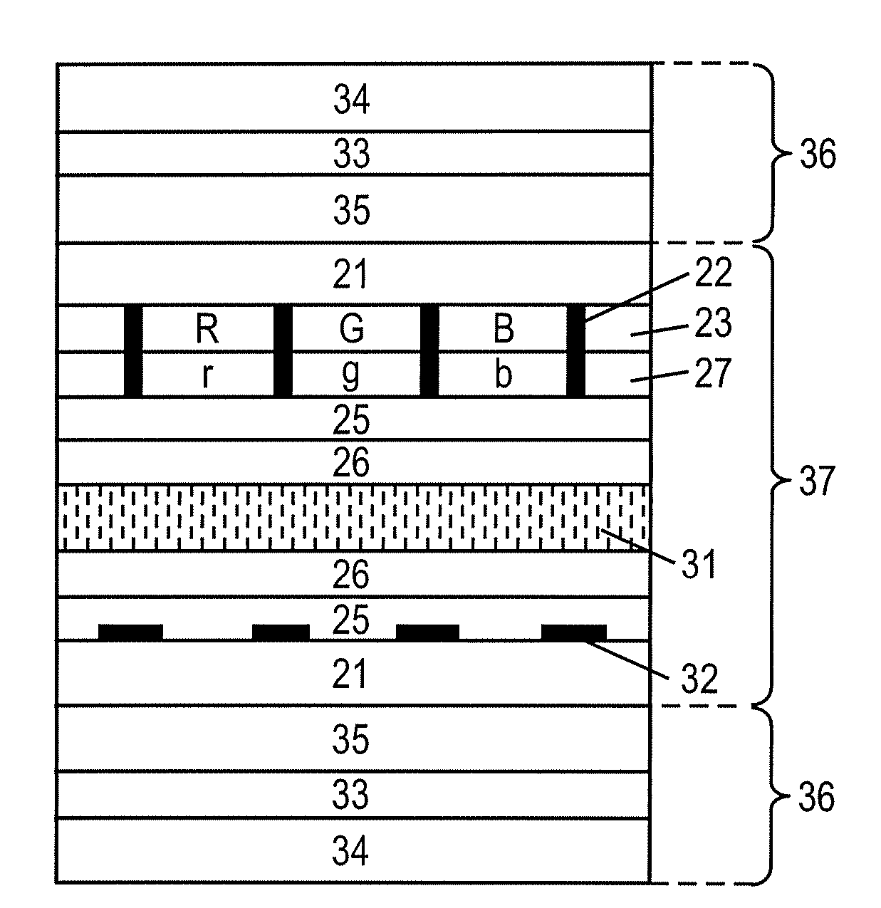
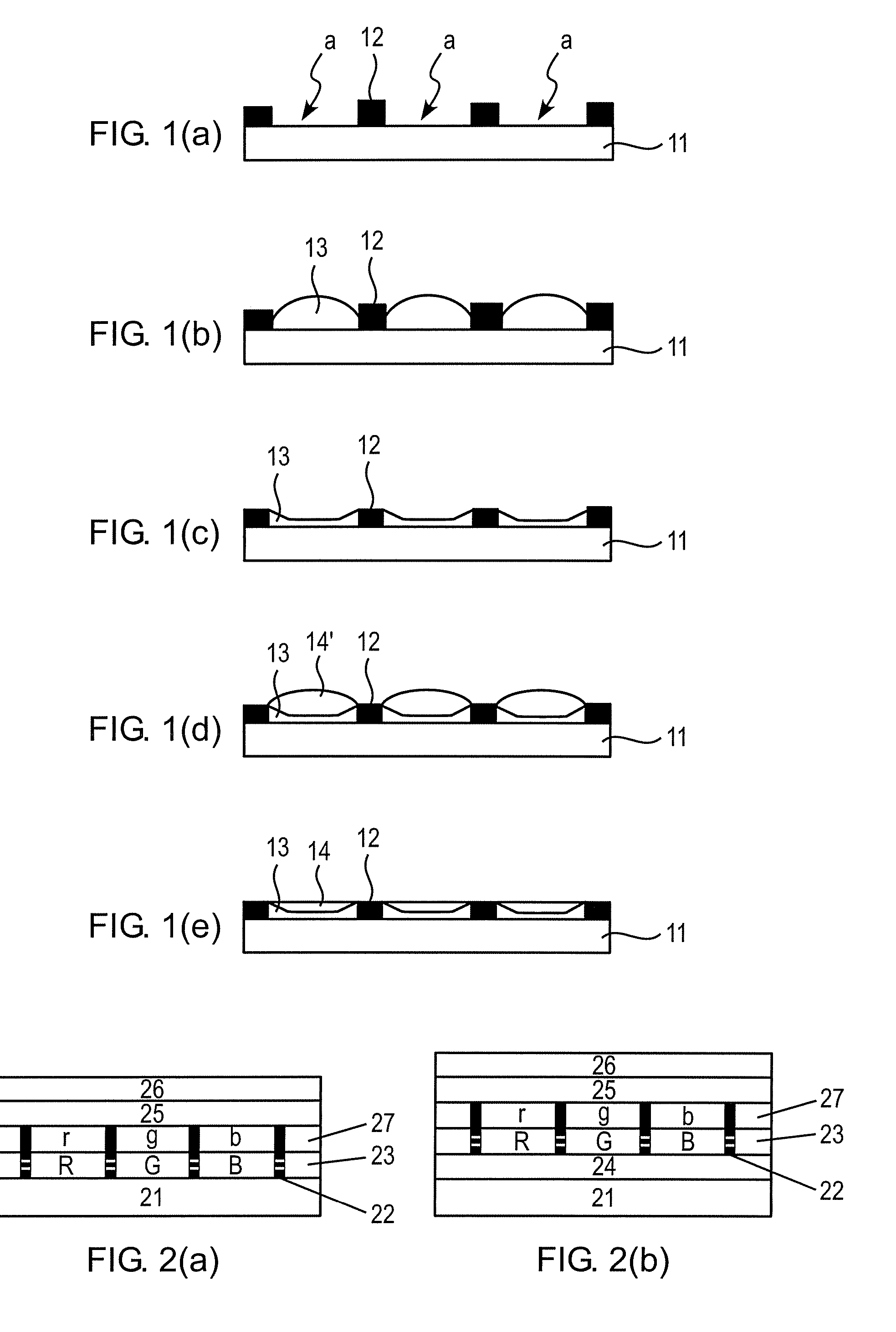
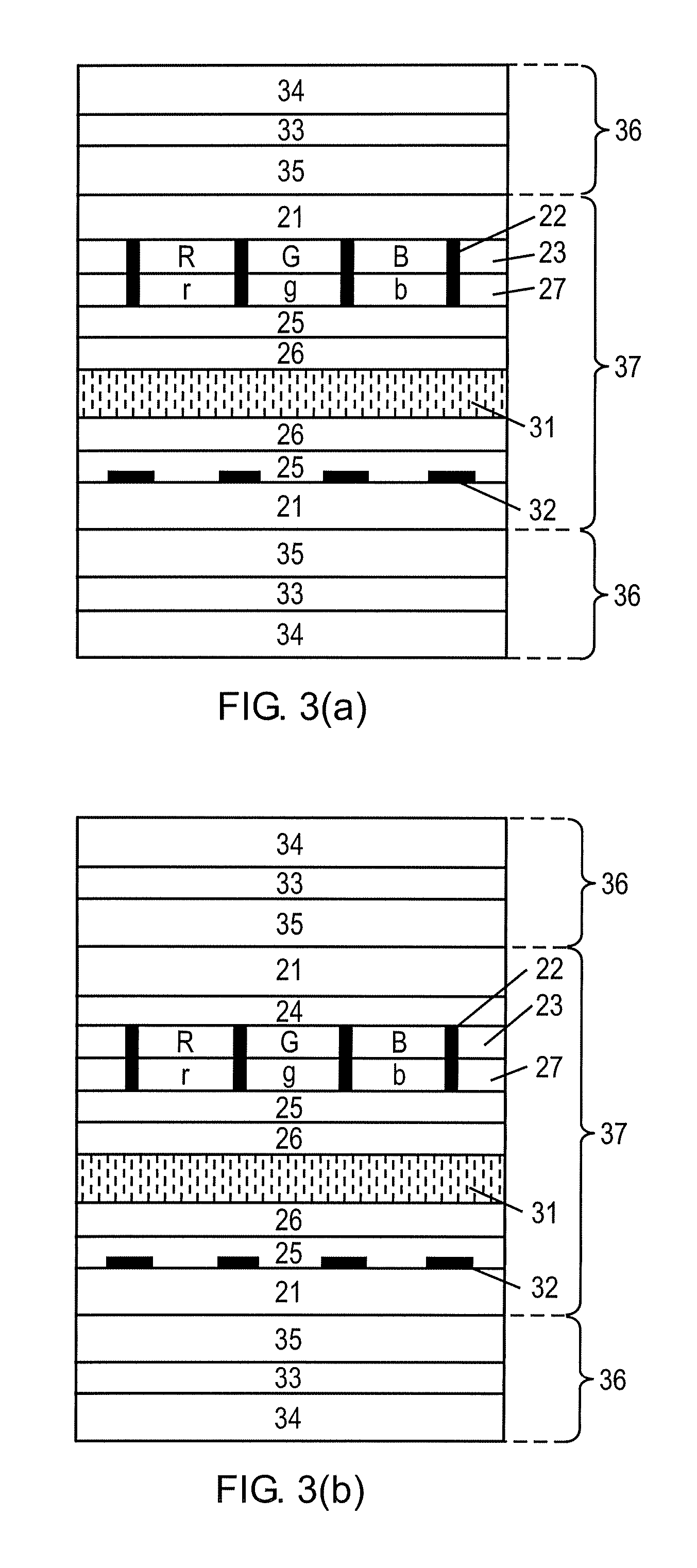
[0207]A substrate composed of non-alkali glass and having a black matrix formed thereon was prepared.
(Preparation of Coating Liquid LC-1 for Forming Optically Anisotropic Layer)
[0208]The composition below was prepared, filtered through a polypropylene filter having a pore size of 0.2 μm, and the filtrate was used as a coating liquid LC-1 for forming the optically anisotropic layer.
[0209]LC-1-1 was synthesized according to the method described in Tetrahedron Lett., Vol. 43, p. 6793 (2002).
Formulation of Coating Liquid for Forming OpticallyAnisotropic layer (% by mass)P-1 having weight-average molecular weight of 45,00025.01.4-Butanediol diacetate74.98Horizontal-alignment aid (LC-1-1)0.02
(Composition for Forming Color Filter)
[0210]Compositions for forming the R, G and B layers, having formulations listed in Table 2, were respectively prepared.
TABLE 2% by massPP-R1PP-G1PP-B1R pigment dispersion-144——R pigment dispersion-25.0——G ...
example 2
[0233]A VA-LCD of Example 2 was fabricated similarly to as in Example 1, except that Optically anisotropic layers R-1, G-1, B-1 were omitted, and instead an optically anisotropic layer of 2.7 μm thick was formed using Coating liquid LC-1 on a protective film to be disposed the liquid crystal cell side of the lower polarizer plate, by a similar method by which the optically anisotropic layer G-1 was fabricated.
[Evaluation of VA-LCDs in Examples 1 and 2]
[0234]Quality of the black state of each of the fabricated liquid crystal display devices was observed at a viewing angle expressed by an azimuth angle of 45° and a polar angle of 60°, and color shift between a viewing angle expressed by an azimuth angle of 45° and a polar angle of 60°, and a viewing angle expressed by an azimuth angle of 180° and a polar angle of 60° was observed.
[0235]It was confirmed from the observation of the fabricated liquid crystal display devices of Examples 1 and 2, that neutral black state was achieved both ...
example 3
Preparation of Coating Liquid LC-2 for Forming Optically Anisotropic Layer
[0236]Coating liquid LC-2 for forming the optically anisotropic layer was prepared similarly to Coating liquid LC-1 for forming the optically anisotropic layer of Example 1, except that Compound P-1 having a weight-average molecular weight of 15,000 was used in place of Compound P-1 having a weight-average molecular weight of 45,000 used in Example 1.
(Fabrication of Optically Anisotropic Layer)
[0237]Similarly to as described in Example 1, the coating liquid LC-2 for forming the optically anisotropic layer obtained in the above was applied using a piezoelectric head to the recesses corresponded to the R, G and B layers surrounded by the light-shielding partition, and was then dried under heating at 140° C. for 2 minutes. The layer was irradiated with polarized light (illumination intensity=200 mW / cm2, energy of irradiation=200 mJ / cm2), the heated again at 130° C., to thereby form Optically anisotropic layers R-...
PUM
| Property | Measurement | Unit |
|---|---|---|
| thickness | aaaaa | aaaaa |
| angle | aaaaa | aaaaa |
| wavelength | aaaaa | aaaaa |
Abstract
Description
Claims
Application Information
 - R&D
- Intellectual Property
- Life Sciences
- Materials
- Tech Scout
- Unparalleled Data Quality
- Higher Quality Content
- 60% Fewer Hallucinations
Browse by: Latest US Patents, China's latest patents, Technical Efficacy Thesaurus, Application Domain, Technology Topic, Popular Technical Reports.
© 2025 PatSnap. All rights reserved.Legal|Privacy policy|Modern Slavery Act Transparency Statement|Sitemap|About US| Contact US: help@patsnap.com


