Thermal transfer image-receiving sheet and method for producing the same
Inactive Publication Date: 2009-04-02
DAI NIPPON PRINTING CO LTD
View PDF11 Cites 3 Cited by
Summary
Abstract
Description
Claims
Application Information
AI Technical Summary
This helps you quickly interpret patents by identifying the three key elements:
Problems solved by technology
Method used
Benefits of technology
Benefits of technology
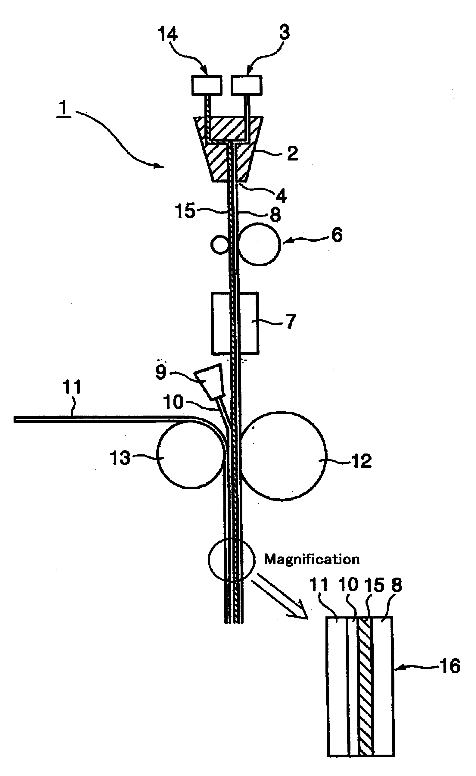
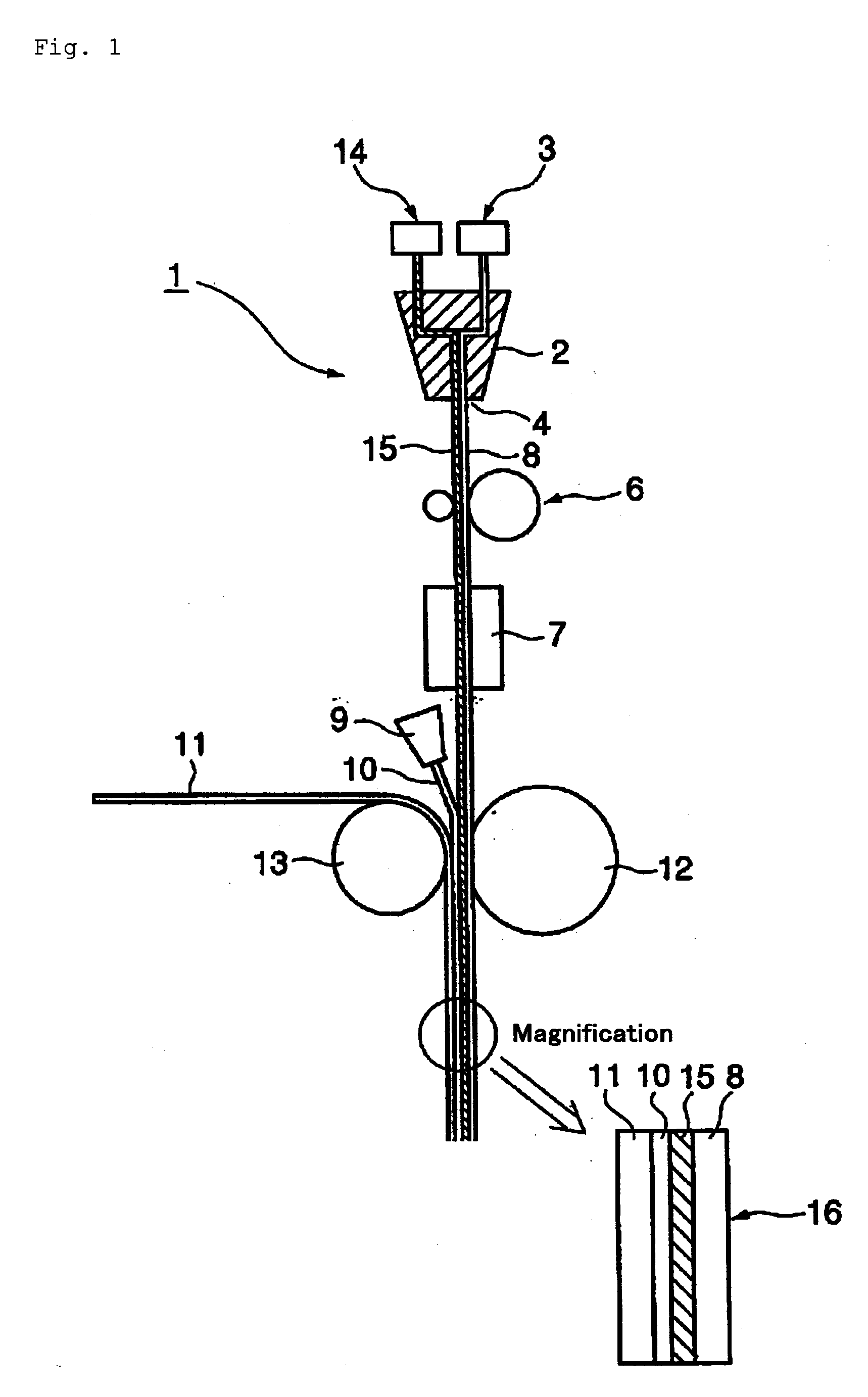
[0048]The method of producing a thermal transfer image-receiving sheet of the present invention is a method in which an insulating layer and an image-receiving layer are formed in this order on a substrate or a good adhesive layer, an insulating layer and an image-receiving layer are formed in this order on a substrate, and a method of producing a thermal transfer image-receiving sheet by melt-coextruding two layers of the insulating layer including a thermoplastic resin (A) and a resin or filler which is not compatible with the thermoplastic resin (A) and the image-receiving layer including a thermoplastic resin (B) such as polyester resin, or three layers of the good adhesive layer including a thermoplastic resin (C), the insulating layer including a thermoplastic resin (A) and a resin or filler which is not compatible with the thermoplastic resin (A) and the image-receiving layer including a thermoplastic resin (B) to form a film, and then stretching this melt-coextruded film to form a layered body of a film, and then laminating the layered body on a substrate with the insulating layer (good adhesive layer) side of the layered body faced with the substrate.
[0049]The above-mentioned method of producing a thermal transfer image-receiving sheet does not use a solvent for dilution or forming a solution as desired in the steps including the step of forming a good adhesive layer, the step of forming an insulating layer and the step of forming an image-receiving layer, and the step of laminating the film on a substrate, and can realize substantially solvent-free production steps, and has high safety in working environment, exhaust emission and the like. Furthermore, when solvent-free production steps are realized, speedups of the production steps are promoted since drying of the solvent is unnecessary.
[0050]Since the thermal transfer image-receiving sheet of the present invention is subjected to melt-extrusion and stretching treatment, the resin or filler, which is not compatible with the thermoplastic resin (A) composing the insulating layer, generates cavities at the boundary face with the thermoplastic resin (A) in the thermoplastic resin (A) of the insulating layer. That is, this thermal transfer image-receiving sheet forms voids in the insulating layer, and thereby the heat resistance and the cushioning property of the insulating layer are improved and high-density and high-resolution images in a printed substance are achieved.
Problems solved by technology
In order to form print images of high quality at a high speed on the image-receiving sheet by such a sublimation thermal transfer printer, an image-receiving layer predominantly composed of a dye-dyeable resin is provided on the substrate, but when paper such as a coated paper or an art paper is used as a substrate of the image-receiving sheet, the image-receiving sheet has a drawback that the sensitivity of receiving a dye for forming images is low because it has relatively high thermal conductivity.
But, when these films are used, the step of laminating an image-receiving layer on a biaxially stretched film is further required, and this method has disadvantages that production efficiency is low and product cost is significantly increased.
However, since the above-mentioned receiving layer does not have voids, a heat-insulating property of the layer is not sufficient, and a level of the image density in a printed substance on which images are formed is not satisfactory.
However, in this image-receiving sheet, since both the cushion layer and the dye-receiving layer do not have voids, a heat-insulating property of the layers is not sufficient, and a level of the image density in a printed substance on which images are formed is not satisfactory.
Method used
Image
Click on the blue label to locate the original text in one second.
Reading with bidirectional positioning of images and text.
Examples
experimental example 1
[0118]A material of a receiving layer and a material of an insulating layer, consisting of the following composition, respectively, were melt-coextruded in thicknesses of 36 μm and 360 μm, respectively, and the resulting coextruded film was stretched by 9 times in terms of a material area with a biaxial stretching machine manufactured by Toyo Seiki Seisaku-sho, Ltd., and the stretched film was subjected to heat setting at 240° C. while chucking the film in both directions to obtain a receiving layer / insulating layer film of 44 μm in thickness having voids which are minute cavities in the insulating layer.
(Material of Receiving Layer)
[0119]Polyester resin (SI-173, produced by Toyobo Co., Ltd.)
[0120]100 parts
Silicone oil (X-22-3939A, produced by Shin-Etsu Chemical Co., Ltd.) 1 part
(Material of Insulating Layer)
[0121]Polyester resin (SI-173, produced by Toyobo Co., Ltd.)
[0127]A material of a receiving layer, a material of an insulating layer and a good adhesive layer, consisting of the following composition, respectively, were melt-coextruded in thicknesses of 36 μm, 360 μm and 36 μm, respectively, and the resulting coextruded film was stretched by 9 times in terms of a material area with a biaxial stretching machine manufactured by Toyo Seiki Seisaku-sho, Ltd. to obtain a receiving layer / insulating layer / good adhesive layer film of 48 μm in thickness having voids which are minute cavities in the insulating layer.
(Material of Receiving Layer)
[0128]Polyester resin (SI-173, produced by Toyobo Co., Ltd.)
[0129]100 parts
Silicone oil (X-22-3939A, produced by Shin-Etsu Chemical Co., Ltd.) 1 part
(Material of Insulating Layer)
[0130]Polyester resin (SI-173, produced by Toyobo Co., Ltd.)
[0135]A thermal transfer image-receiving sheet of Experimental Example 3 was prepared by following the same procedure as in Experimental Example 1 except for changing the material of the insulating layer of Experimental Example 1 to the following composition.
(Material of Insulating Layer)
[0136]Polyester resin (SI-173, produced by Toyobo Co., Ltd.)
[0137]80 parts
Silicone filler (KMP-590, produced by Shin-Etsu Chemical Co., Ltd.) 20 parts
PUM
Property
Measurement
Unit
Fraction
aaaaa
aaaaa
Ratio
aaaaa
aaaaa
Thermal properties
aaaaa
aaaaa
Abstract
It is an object of the present invention to provide a high performance and highly productive thermal transfer image-receiving sheet which solves drawbacks of the prior art, i.e., drawbacks such as the deterioration in sensitivity in using a pulp paper such as a coated paper as a substrate, and the reduction in productivity and the increase in cost in using a laminated and bonded sheet of a void-containing biaxially stretched film and a core material, is inexpensive, and can attain high-density and high-resolution images having no density irregularity and dot missing.A method of producing a thermal transfer image-receiving sheet in which at least an insulating layer 15 and an image-receiving layer 8 are formed in this order on a substrate 11, comprising the steps ofmelt-coextruding the insulating layer including a thermoplastic resin (A) and a resin or filler which is not compatible with the thermoplastic resin (A) and the receiving layer including a thermoplastic resin (B) to form a film, and then stretching this melt-coextruded film to form a layered body of a film, and then laminating the layered body on a substrate with the insulating layer side of the layered body faced with the substrate,wherein said image-receiving layer or a release layer provided on said image-receiving layer side of said layered body contains modified silicone oil andthe void fraction of the insulating layer is 15 to 65%.
Description
TECHNICAL FIELD[0001]The present invention relates to a thermal transfer image-receiving sheet which is used with a thermal transfer sheet of sublimation dye transfer and a method of producing the same, and more particularly to a thermal transfer image-receiving sheet which can be used in the area of a wide variety of color printers such as a video printer and the like and has a high print density and good productivity, and a method of producing the same.BACKGROUND ART[0002]Hitherto, various thermal transfer methods have been publicly known, and among these methods, a method, in which a sublimation dye is used as a recording material and it is supported on a substrate sheet of paper, a plastic film or the like to form a thermal transfer sheet, and various full color images are formed on a thermal transfer image-receiving sheet which can be dyed with a sublimation dye, for example, a thermal transfer image-receiving sheet in which a dye receiving layer is provided on the surface of p...
Claims
Application Information
Patent Timeline
Application Date:The date an application was filed.
Publication Date:The date a patent or application was officially published.
First Publication Date:The earliest publication date of a patent with the same application number.
Issue Date:Publication date of the patent grant document.
PCT Entry Date:The Entry date of PCT National Phase.
Estimated Expiry Date:The statutory expiry date of a patent right according to the Patent Law, and it is the longest term of protection that the patent right can achieve without the termination of the patent right due to other reasons(Term extension factor has been taken into account ).
Invalid Date:Actual expiry date is based on effective date or publication date of legal transaction data of invalid patent.

