Membrane catalyst layer assembly with reinforcing films, membrane electrode assembly with reinforcing files, and polymer electrolyte fuel cells

a membrane electrode and reinforcing film technology, applied in the direction of fuel cell details, electrochemical generators, cell components, etc., can solve the problems of repeated expansion and shrinkage preventing effective use and ultimately breaking the electrolyte membrane, so as to prevent the mechanical strength of the electrolyte membrane or catalyst layer from decreasing, reduce heat, and reduce the pressure applied to the reinforcing film during bonding

Inactive Publication Date: 2009-04-02
DAI NIPPON PRINTING CO LTD
View PDF7 Cites 40 Cited by
  • Summary
  • Abstract
  • Description
  • Claims
  • Application Information

AI Technical Summary

Benefits of technology

[0023]The first bonding layers may be adhesive-bonded to the membrane electrode assembly. When the reinforcing films are adhesive-bonded to the membrane-catalyst layer assembly, the pressure applied to the reinforcing films during bonding can be reduced, as compared to when the reinforcing films are bonded to the membrane-catalyst layer assembly by welding. This can prevent the reinforcing films from sinking into the electrolyte membrane or catalyst layers, thereby preventing the mechanical strength of the electrolyte membrane or catalyst layers from decreasing.
[0024]Each of the reinforcing films may further have a second bonding layer formed on the gas barrier layer, and a gasket may be bonded on the second bonding layer. This ensures that the reinforcing films are bonded to the gaskets. When each reinforcing film also has a second bonding layer, the first bonding layer and the second

Problems solved by technology

Thus, when the polymer electrolyte fuel cells repeatedly generate or do not generate power to subject the electrolyte membrane to repeated moist and dry states, the portions of the electrolyte membrane corresponding to the gap portions experience repeated expansion and shrinkage.
As a result, the electrolyte membrane may become worn, and ultimately be broken.
However, the outer edge portions of the electrolyte membrane provided with the gaskets do not contribute to the generation of power, thus preventing

Method used


Image

  • Membrane catalyst layer assembly with reinforcing films, membrane electrode assembly with reinforcing files, and polymer electrolyte fuel cells
  • Membrane catalyst layer assembly with reinforcing films, membrane electrode assembly with reinforcing files, and polymer electrolyte fuel cells
  • Membrane catalyst layer assembly with reinforcing films, membrane electrode assembly with reinforcing files, and polymer electrolyte fuel cells

Examples


first embodiment

[0058]A first embodiment is described below with reference to the drawings.

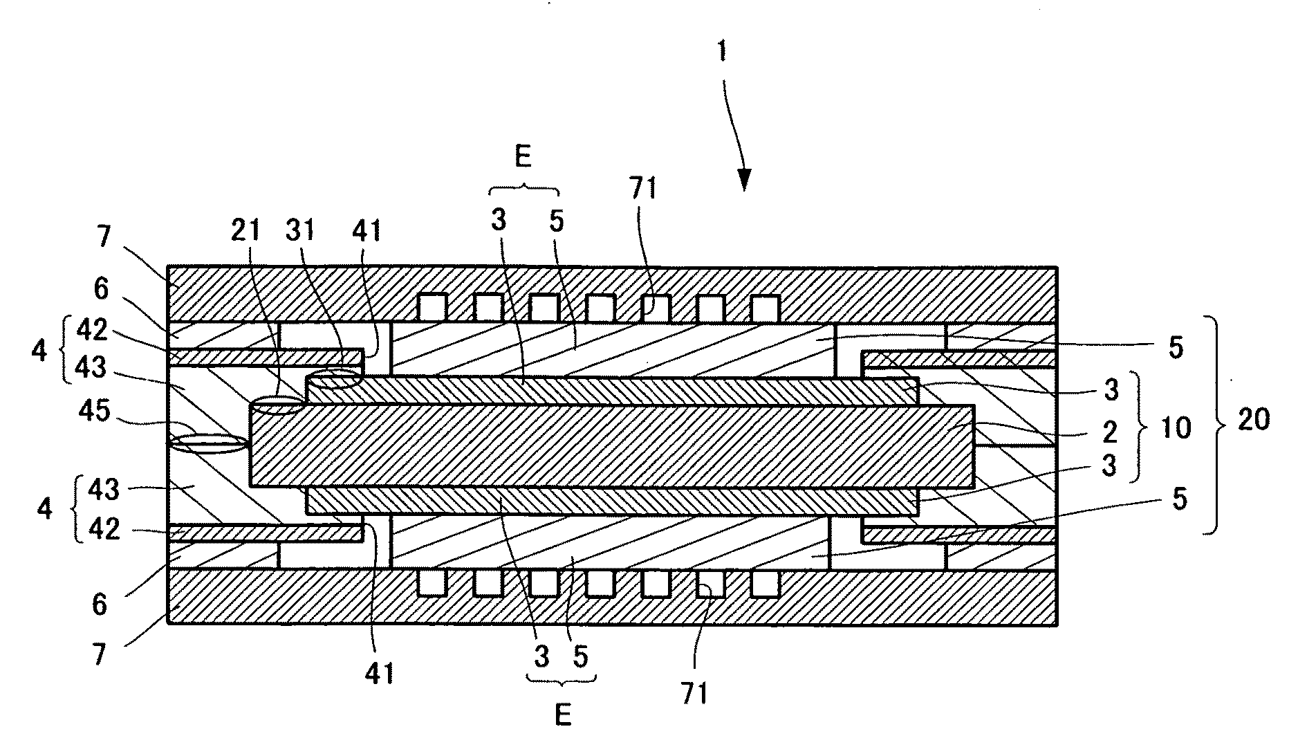
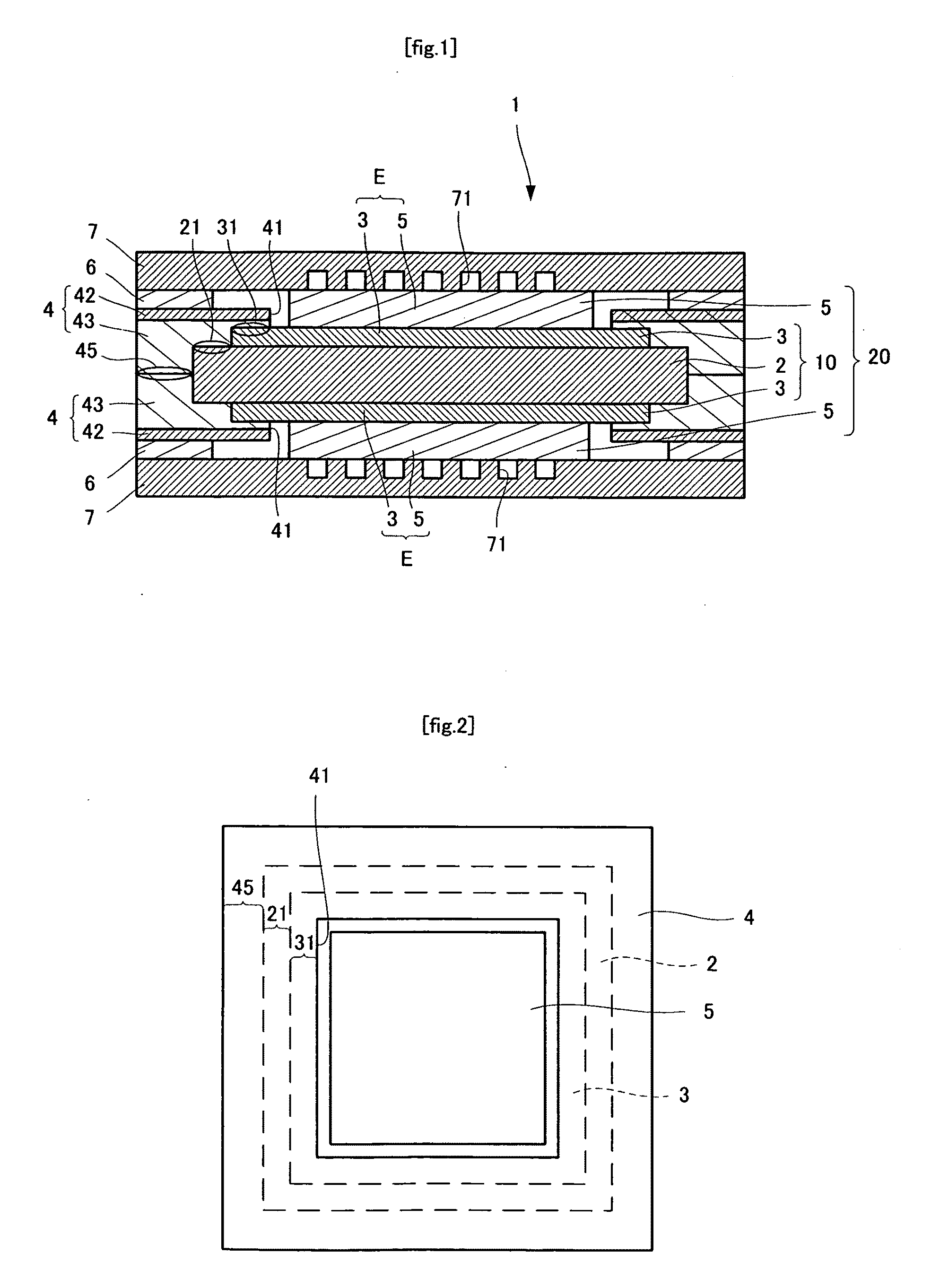
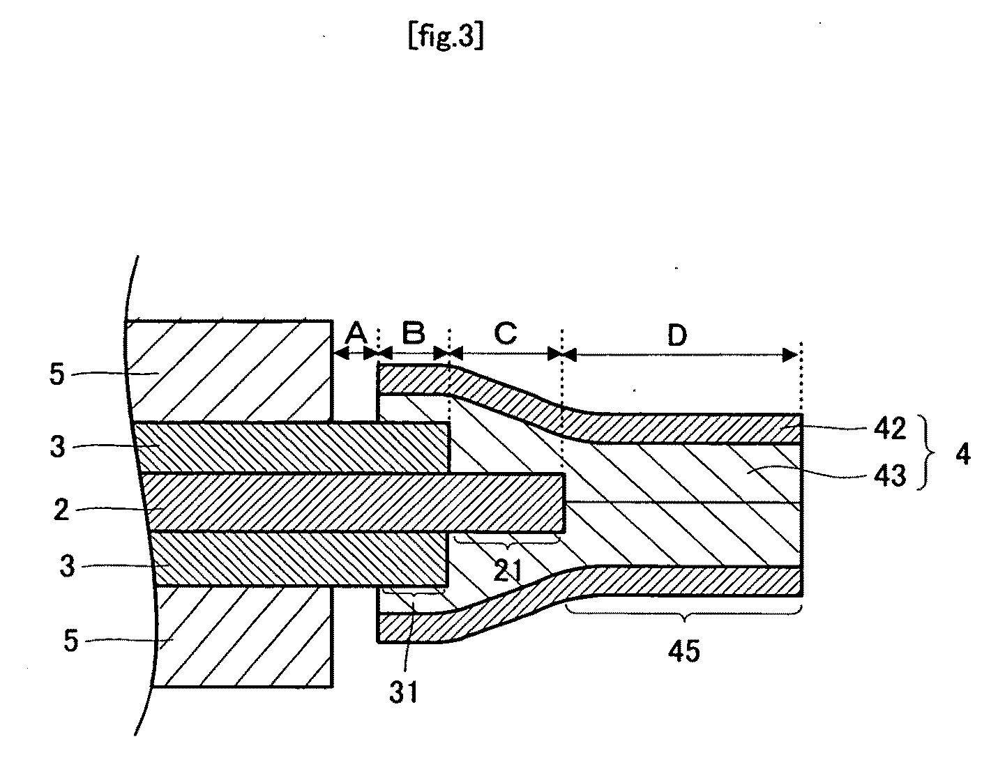
[0059]As shown in FIGS. 1 and 2, a polymer electrolyte fuel cell 1 includes an electrolyte membrane 2 that is rectangular from a plan view. The electrolyte membrane 2 preferably has a thickness of from about 20 to about 250 μm, and more preferably from about 20 to about 80 μm. Catalyst layers 3, which are rectangular from a plan view, and smaller in size than the electrolyte membrane 2, are formed on upper and lower surfaces of the electrolyte membrane 2. The catalyst layers 3 preferably have a thickness of from about 10 to about 100 μm. and more preferably from about 20 to about 50 μm. The assembly wherein the catalyst layers 3 are formed on both surfaces of the electrolyte membrane 2 is referred to as a membrane-catalyst layer assembly 10. Because the catalyst layers 3 are smaller than the electrolyte membrane 2, they are not formed on outer edge portions 21 of the electrolyte membrane 2. Distance C from th...

second embodiment

[0083]A second embodiment is described below with reference to the drawings, with emphasis on features of the second embodiment different from those of the first embodiment.

[0084]As shown in FIGS. 6 and 7, the polymer electrolyte fuel cell 1′ includes a membrane-catalyst layer assembly 10, which is identical to that of the first embodiment. On each of catalyst layers 3 of the membrane-catalyst layer assembly 10 lies a gas diffusion layer 5 that is rectangular from a plan view. Each catalyst layer 3 and each gas diffusion layer 5 constitute an electrode E. The gas diffusion layer 5 is substantially identical in size to the catalyst layer 3, or is smaller than the catalyst layer 3. Distance F from the outer edge of the gas diffusion layer 5 to the outer edge of the catalyst layer 3 (see FIG. 8) is preferably from about 0 to about 5 mm. The assembly wherein the gas diffusion layers 5 are formed on both catalyst layers 3 of the membrane-catalyst layer assembly 10 is referred to as a mem...

example 1

[0101]A polymer electrolyte fuel cell as shown in FIG. 1 was prepared as follows.

[0102]A 53 μm thick NRE212CS (manufactured by Dupont) cut to a size of 63×63 mm was used as an electrolyte membrane 2.

[0103]Transfer sheets 8 for forming catalyst layers were then prepared as follows. First, 10 g of 1-butanol, 10 g of 3-butanol, 20 g of a fluororesin (a 5 wt % Nafion binder, manufactured by Dupont), and 6 g of water were added to 2 g of carbon with a platinum catalyst supported thereon (platinum content: 45.7 wt %; Tanaka Kikinzoku Group, TEC10E50E). These components were mixed using a dispersion machine to prepare an ink composition for forming catalyst layers. The ink composition for forming catalyst layers was then applied to polyester films (manufactured by Toray, X44, film thickness: 25 μm) so that the catalyst layers after drying had a platinum weight of 0.4 mg / cm2, thereby preparing transfer sheets 8 for forming catalyst layers.

[0104]The thus prepared transfer sheets 8 for formin...


PUM


Abstract

A membrane-catalyst layer assembly with reinforcing films including a solid polymer electrolyte membrane 2, a catalyst layer 3 formed on each surface of the electrolyte membrane 2, and a reinforcing film 4 located on each surface of a membrane-catalyst layer assembly having the electrolyte membrane and the catalyst layers. Each of the reinforcing films 4 has a frame shape with a central opening 41. Each of the catalyst layers 3, except for an outer edge portion 31, is exposed through the opening 41. Each reinforcing film 4 has a first bonding layer 43 bonded to a membrane-catalyst layer assembly 10, and a gas barrier layer 42 formed on the first bonding layer 43 to prevent passage of a fuel gas and an oxidant gas.

Description

BACKGROUND OF THE INVENTION[0001](1) Field of the Invention[0002]The present invention relates to a membrane-catalyst layer assembly with reinforcing films, a membrane electrode assembly with reinforcing films, and polymer electrolyte fuel cells.[0003](2) Description of the Related Art[0004]Fuel cells include electrodes on both surfaces of an electrolyte, and generate power utilizing the electrochemical reaction between hydrogen and oxygen, thus producing only water during the generation of power. Unlike conventional internal combustion engines, fuel cells do not emit environmentally harmful gases such as carbon dioxide and the like, and are therefore expected to prevail as next-generation clean energy systems. Among these fuel cells, polymer electrolyte fuel cells, in particular, have low operating temperatures and low electrolyte resistance, and provide high power while being small because they use highly activated catalysts. For this reason, polymer electrolyte fuel cells are exp...

Claims


Application Information

Patent Timeline
IPC IPC(8): H01M8/10
CPCH01M4/881H01M8/0273H01M8/0276H01M8/0284H01M8/1004H01M8/0291H01M8/0297Y02E60/50H01M8/0286H01M4/8814H01M8/0289H01M8/0258
Inventor YOSHIDA, AKIHIROMITSU, MASASHI
Owner DAI NIPPON PRINTING CO LTD
Why Eureka
Try Eureka