Structure and method for determining an overlay accuracy

a technology of overlay accuracy and structure, applied in the field of integrated circuit fabrication, can solve the problems of deviation from ideal registration, uncertainty in overlaying the image of the pattern of the current material layer, and variations in etched features, so as to achieve the effect of simplifying the measurement algorithm and recipe setup, and increasing the amount of position information obtained during a single measurement even

Inactive Publication Date: 2009-04-02
GLOBALFOUNDRIES US INC
View PDF5 Cites 54 Cited by
  • Summary
  • Abstract
  • Description
  • Claims
  • Application Information

AI Technical Summary

Benefits of technology

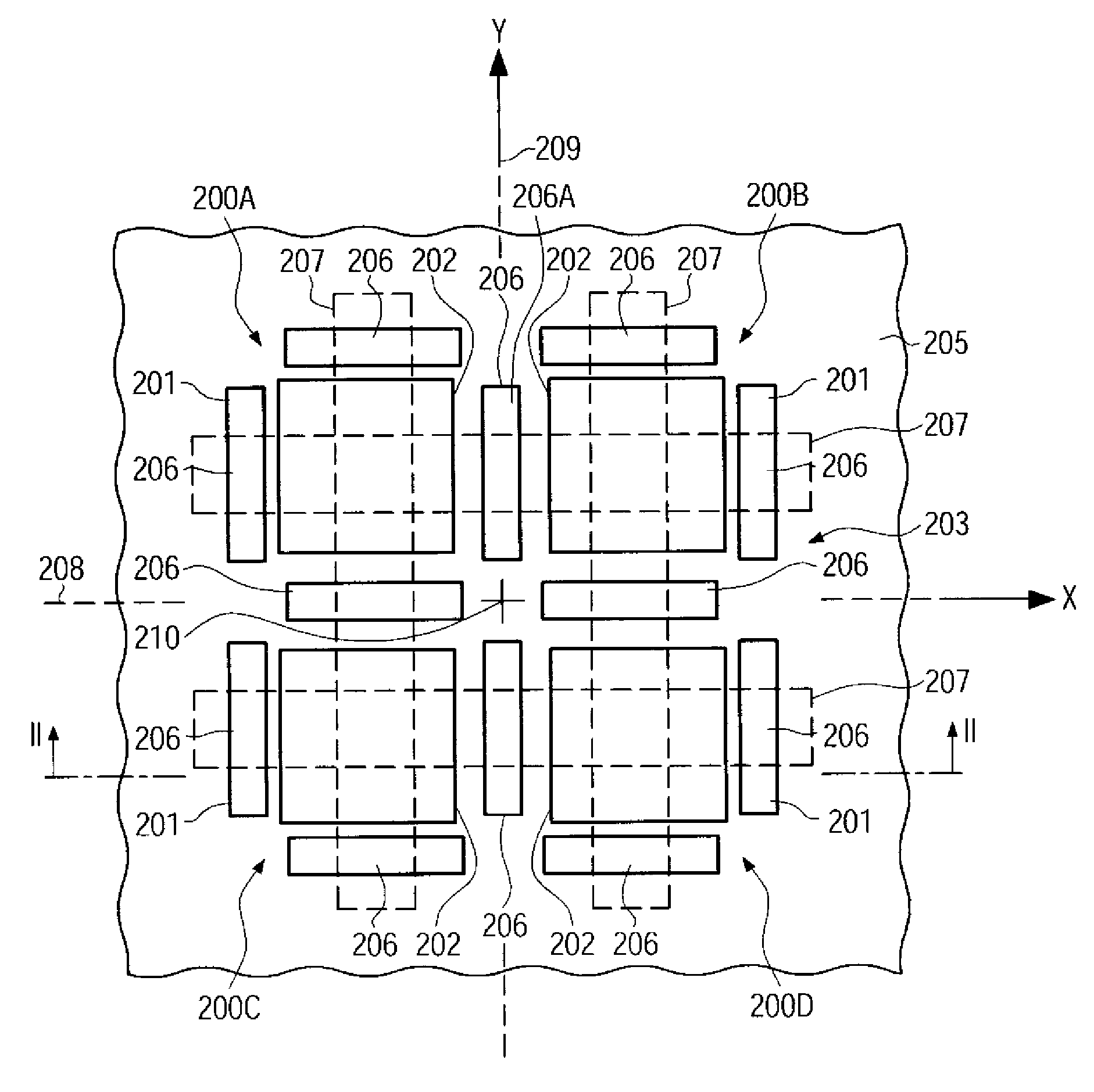
[0017]Generally, the present disclosure is directed to a technique that enables the evaluation of positional errors during the formation of microstructural features, such as integrated circuits and the like, wherein, in some illustrative embodiments, a measurement algorithm and recipe setup may be simplified compared to conventional techniques, while at the same time, in some illustrative embodiments, the amount of position information obtained during a single measurement event may be increased. For this purpose, a overlay target structure is provided that is invariant to a geometric transformation, for instance, rotation about a predetermined angle or reflection, enabling, in an illustrative embodiment, to obtain information about positioning errors within a predefined measurement site that may be accessed during a single measurement cycle. The overlay target structure may include an overlay target assembly comprising at least two targets. Herein, “reflection” denotes a mathematical map that transforms an object under consideration, e.g., the target structure, into its mirror image, whereas a rotation of an object about a predetermined angle relates to a rotation of the object about a rotation axis.

Problems solved by technology

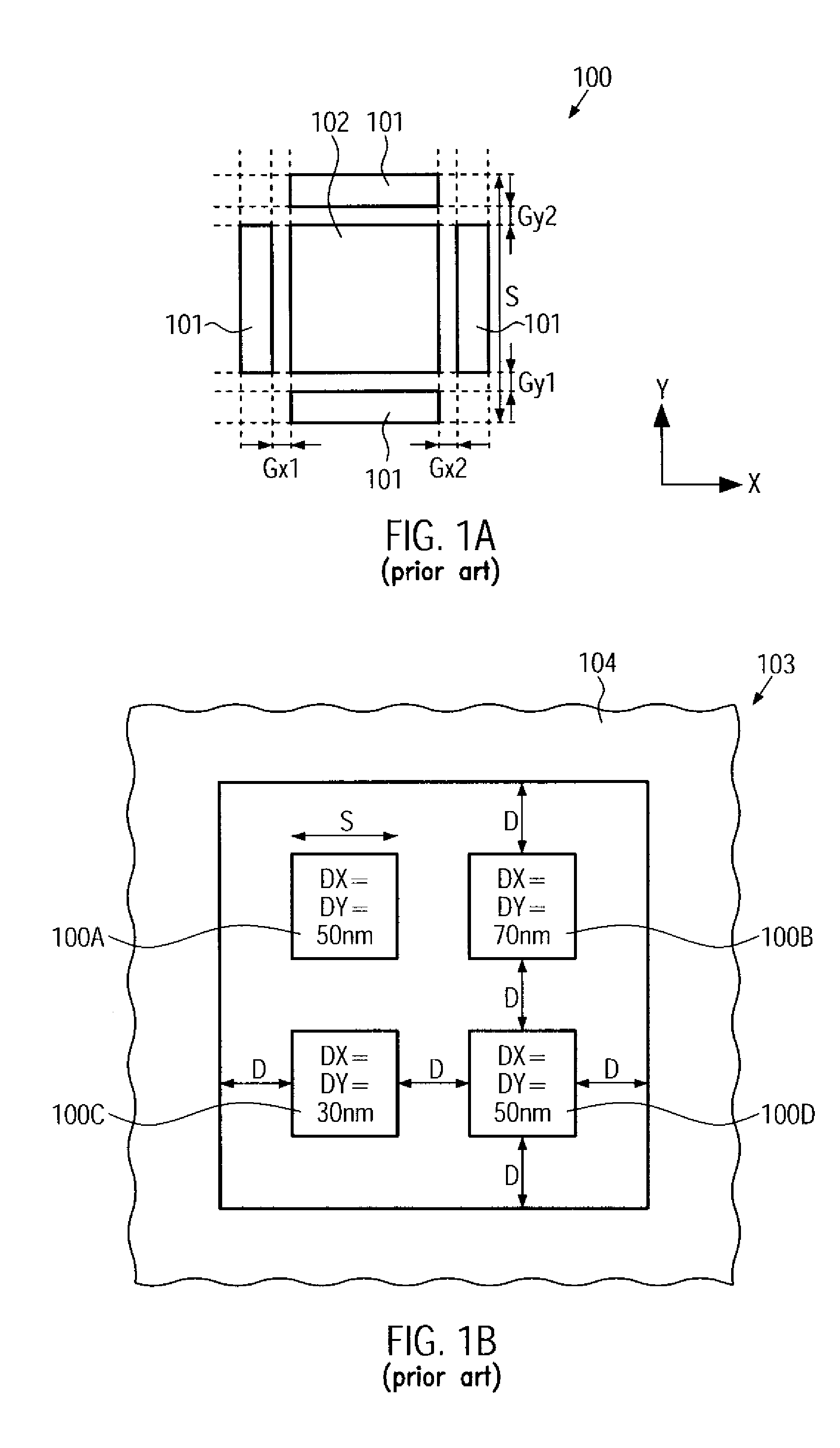
Deviations from an ideal registration are caused by, for example, a variation of a photoresist image on the substrate due to non-uniformities in such parameters as resist thickness, temperature, exposure dose, time and developing conditions.
Furthermore, non-uniformity of the etch processes may also lead to variations in the etched features.
In addition, there exists an uncertainty in overlaying the image of the pattern of the current material layer to the etched or otherwise defined pattern of the previously formed material layer while photolithographically transferring the image of the photo mask onto the substrate.
Several factors contribute to the inability of the imaging system to perfectly overlay two layers, such as imperfections within a set of masks, temperature differences at the different times of exposure and limited registration capability of the alignment tool.
For ever-decreasing feature sizes of microstructures, however, the detection of a displacement and thus the quantification of an overlay error between both overlay marks on the basis of edge finding routines may no longer be adequate.
With decreasing feature sizes, however, a discrepancy between overlay characteristics within a single die and the significant larger overlay marks may be observed, thereby rendering measuring data obtained from the target less reliable.
Consequently, an overlay accuracy with respect to the x- and y-directions may be estimated with moderately high precision for the overlay measurement structure itself, but may not permit a precise estimation of the overlay accuracy within actual die regions having formed therein structural features of significantly less critical dimensions compared to dimensions in the overlying measurement structure.
However, recent studies have indicated that the discrepancies from field linearity may no longer be negligible for sophisticated overlay control requirements, e.g., at 65 nm technology.
For example, scanner lens distortion differences and reticle registration are known as major contributors to intrafield overlay errors.
With no noise in the signal, the response is linear, but noise causes the response of the image symmetry as a function of the overlay error to tail off for small overlay offsets.

Method used


Image

  • Structure and method for determining an overlay accuracy
  • Structure and method for determining an overlay accuracy
  • Structure and method for determining an overlay accuracy

Examples


Embodiment Construction

[0033]Various illustrative embodiments of the invention are described below. In the interest of clarity, not all features of an actual implementation are described in this specification. It will of course be appreciated that in the development of any such actual embodiment, numerous implementation-specific decisions must be made to achieve the developers' specific goals, such as compliance with system-related and business-related constraints, which will vary from one implementation to another. Moreover, it will be appreciated that such a development effort might be complex and time-consuming, but would nevertheless be a routine undertaking for those of ordinary skill in the art having the benefit of this disclosure.

[0034]The present subject matter will now be described with reference to the attached figures. Various structures, systems and devices are schematically depicted in the drawings for purposes of explanation only and so as to not obscure the present disclosure with details ...


PUM

PropertyMeasurementUnit
rotationaaaaaaaaaa
rotationaaaaaaaaaa
sizeaaaaaaaaaa

Abstract

An enhanced technique for determination of an alignment accuracy involves an overlay target assembly which comprises at least two targets, each target having a first sub-structure of a first layer and a second sub-structure of a second layer, wherein, when the first layer and the second layer are correctly aligned, the first sub-structure and the second sub-structure of at least one of the targets are offset with respect to each other by a programmed offset and the overlay target assembly is invariant to at least one geometric transformation. If the offset vectors which describe the offset between the first sub-structure and the second sub-structure all have the same norm, the overlay error may be determined without calibration. Redundancy may be increased by providing each target with two or more programmed offsets between elements of the first sub-structure and elements of the second sub-structure.

Description

BACKGROUND OF THE INVENTION[0001]1. Field of the Invention[0002]The present subject matter generally relates to the field of fabrication of integrated circuits, and, more particularly, to a structure and a method for determining an overlay accuracy, that is, an alignment accuracy, between two layers of a multi-layered device.[0003]2. Description of the Related Art[0004]In the semiconductor industry, there is a continuing trend toward higher device densities. To achieve these high densities, there has been and continues to be efforts towards scaling down device dimensions. Hence, the fabrication of microstructures, such as integrated circuits, requires tiny regions of precisely controlled size to be formed in a material layer over an appropriate substrate, such as a silicon substrate, a silicon-on-insulator (SOI) substrate or other suitable carrier materials. These tiny regions of precisely controlled size are generated by patterning the material layer by performing photolithography,...

Claims


Application Information

Patent Timeline
Patent Type & Authority Applications(United States)
IPC IPC(8): G03F1/00
CPCY10S438/975G03F7/70633
Inventor SCHULZ, BERND
Owner GLOBALFOUNDRIES US INC
Why Eureka
Try Eureka