Process for producing liqefied natural gas from high co2 natural gas

a natural gas and high co2 technology, applied in the direction of liquefaction, gaseous fuels, lighting and heating apparatus, etc., can solve the problems of inability to make a perfect separation between cosub>2/sub> and cosub>2/sub>, and the membrane cannot make a perfect separation between cosub>2 and cosub>2

Inactive Publication Date: 2009-04-09
CHEVROU USA INC
View PDF23 Cites 16 Cited by
  • Summary
  • Abstract
  • Description
  • Claims
  • Application Information

AI Technical Summary

Benefits of technology

[0008]The present invention achieves the advantage of a process for producing LNG from high-CO2 natural gas, with the flexibility of producing separated products such as ethane, propane, and a hydrocarbon condensate.

Problems solved by technology

Amine units operate only under a narrow range of concentrations and acid gas loadings (at a given CO2 partial pressure in the gas phase) due to corrosion limitations.
Because the required amine flowrate is proportional to the amount of CO2 that needs to be removed, amine absorption plants become progressively larger and more expensive with higher CO2 concentrations in the natural gas.
Membranes however, have the similar disadvantage of amine systems in that the CO2 is normally recovered at low pressure.
Further, membranes cannot make a perfect separation between CO2, and hydrocarbons; a small amount of hydrocarbon will always permeate with the CO2.
Thus, the ultimate purity of the CO2 rich product is limited to the order of 97% to perhaps 98%.
Membranes are not able to produce a CO2-rich stream of ultra-high purity, such as on the order of 99.5+%.
However, because the CO2 recovered from the overhead of an amine stripping column is slightly above atmospheric pressure, recompression of that CO2 to a state where it could be readily transported / reinjected may be economically impractical.

Method used


Image

  • Process for producing liqefied natural gas from high co2 natural gas
  • Process for producing liqefied natural gas from high co2 natural gas
  • Process for producing liqefied natural gas from high co2 natural gas

Examples


first embodiment

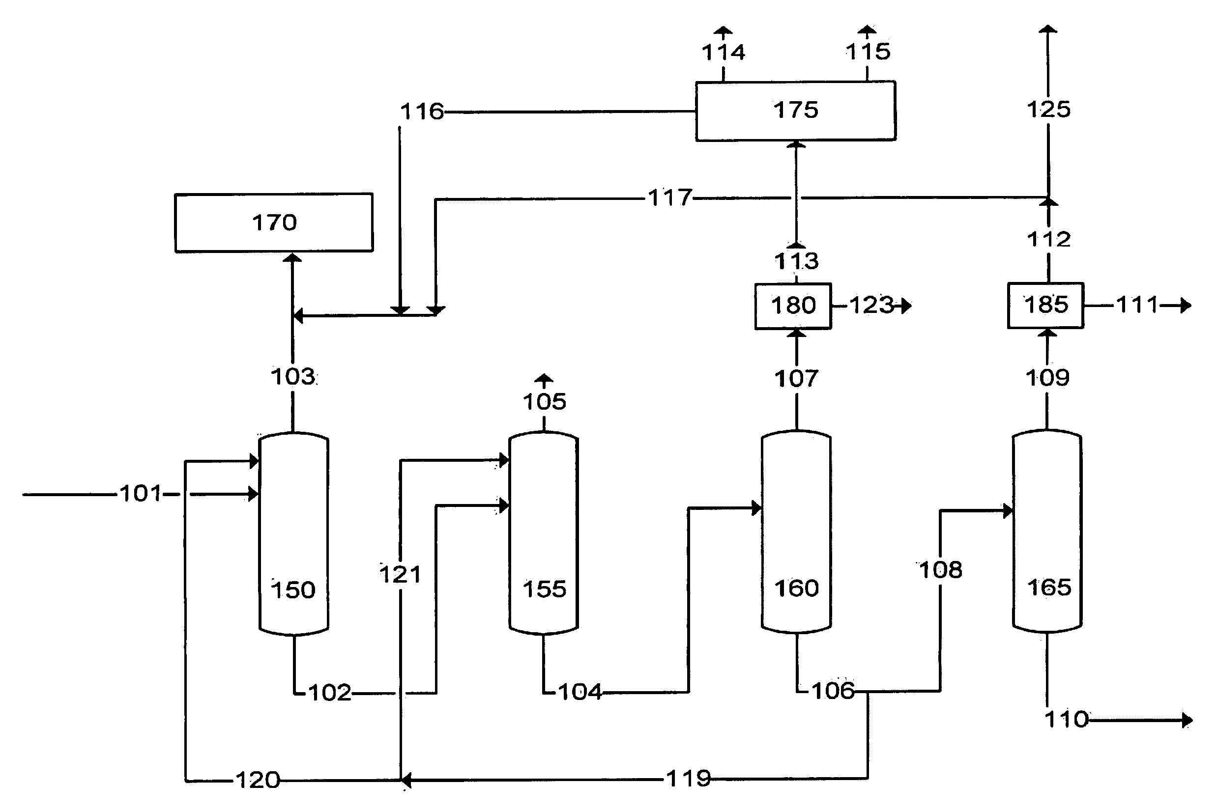
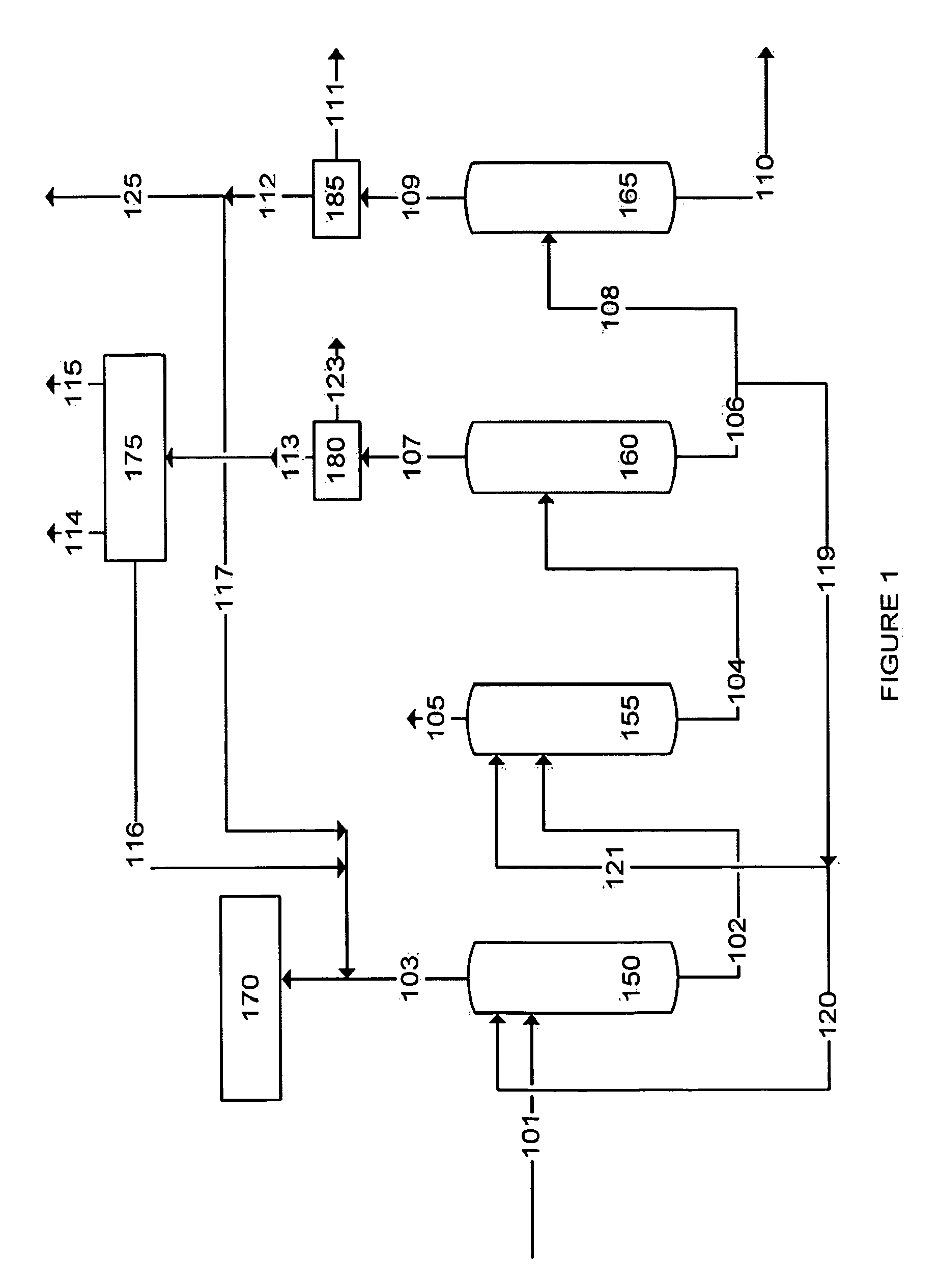
[0034]In an embodiment of the invention illustrated in FIG. 1, a hydrocarbon feed stream 101, having a composition as shown in TABLES 1 & 2 (simulated data), is fed to a demethanizer (DeC1) column 150. The DeC1 column 150 may be a packed or trayed-type distillation column equipped with a bottom reboiler, side reboilers, and a condenser, that is designed to process at least two feed streams: a light hydrocarbon feed gas stream and a heavy hydrocarbon liquid solvent stream. The operating pressure of the DeC1 column is in the range of about 38 to about 45 bar. The operating temperature of the overhead condenser is in the range of about −91 to about −84° C.

[0035]A hydrocarbon recycle stream 120 from the bottoms of a depropanizer (DeC3) column 160 is also fed into the DeC1 column 150. Essentially, the hydrocarbon recycle stream 120 is fractionated gas components passed from the plurality of separation processes as further described below. The hydrocarbon recycle prevents the CO2 from fre...

second embodiment

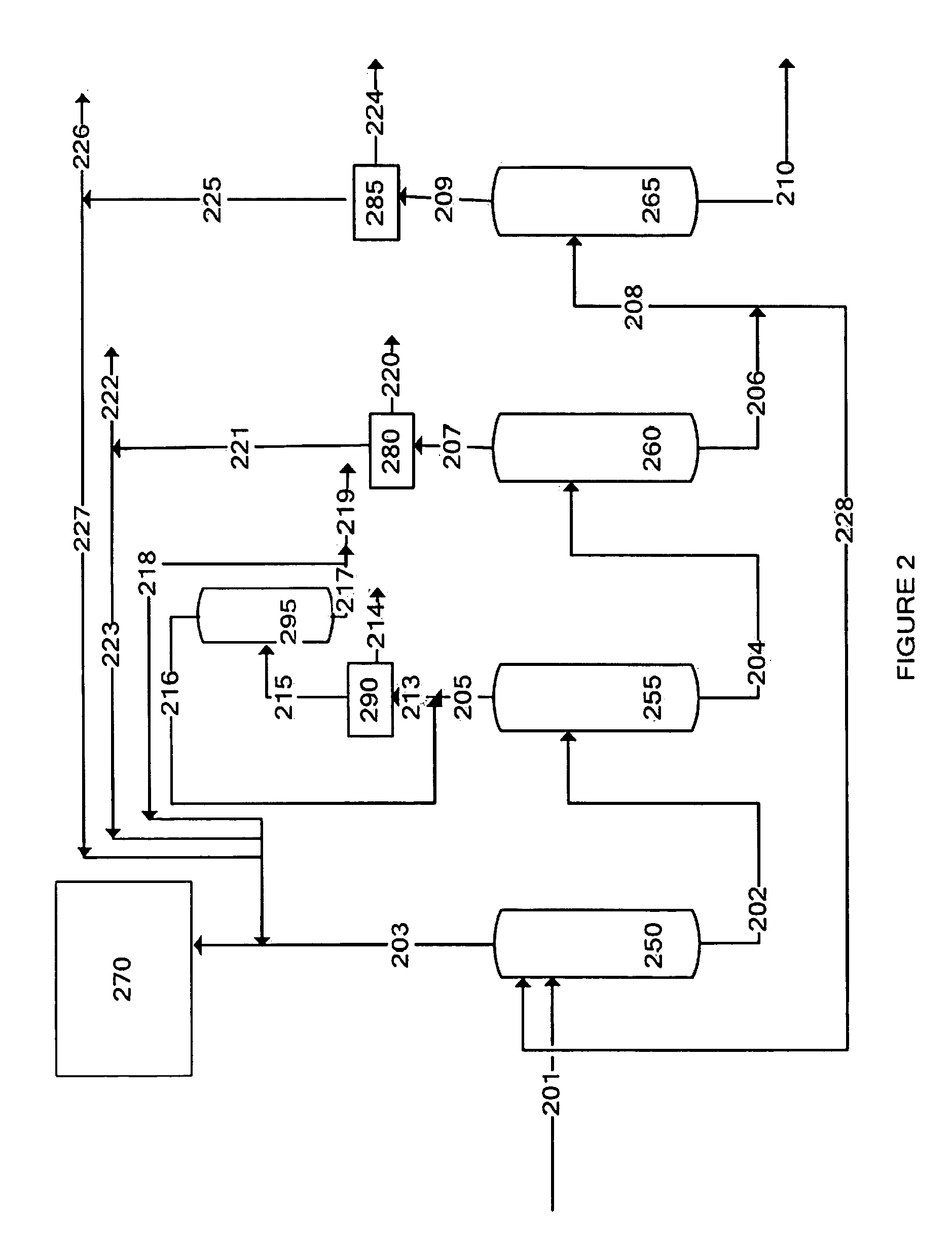
[0051]In another embodiment of the invention as illustrated in FIG. 2, a hydrocarbon feed stream 201, having a composition as shown in TABLES 3 & 4 (simulated data), is fed to a DeC1 column 250. The DeC1 column 250 is similar to that described above. The operating pressure of the DeC1 column 250 is in the range of about 38 to about 45 bar. The operating temperature of the overhead condenser is in the range of about −91 to about −84° C.

[0052]A hydrocarbon recycle stream 228 from the bottoms of a DeC3 column 260 is also fed into the DeC1 column 250. The hydrocarbon recycle prevents the CO2 from freezing and acts as a scrubbing agent to remove aromatics and other heavy hydrocarbons from the C1-rich product stream taken overhead.

[0053]Methane is taken as the principal overhead product, stream 203, and has the composition as shown in TABLE 3. The separated methane contains less than about 100 ppm CO2 and less than about 3 ppm H2S. Also, a full liquid reflux on the separated methane is fe...

third embodiment

[0067]In another embodiment of the invention as illustrated in FIG. 3, a hydrocarbon feed stream 301, having a composition as shown in TABLES 5 & 6 (simulated data), is fed to a DeC1 column 350.

[0068]The DeC1 column 350 is similar to that described above. The operating pressure of the DeC1 column 350 is in the range of about 38 to about 45 bar. The operating temperature of the overhead condenser is in the range of about −91 to about −84° C.

[0069]A hydrocarbon recycle stream 312 from the bottoms of a DeC3 column 360 is also fed into the DeC1 column 350. The hydrocarbon recycle prevents the CO2 from freezing and acts as a scrubbing agent to remove aromatics and other heavy hydrocarbons from the C1-rich product stream taken overhead. Also, a full liquid reflux on the separated methane is fed back to the demethanizer 350.

[0070]Since the aromatics are reduced to such a low level and the temperature is very cold, the majority of stream 303 may be fed to a MCHE 370. The MCHE is similar to ...


PUM

PropertyMeasurementUnit
temperatureaaaaaaaaaa
pressureaaaaaaaaaa
temperatureaaaaaaaaaa

Abstract

A process for producing LNG from high CO2 natural gas. The process includes: separating methane from a hydrocarbon stream containing CO2 to produce a methane-depleted hydrocarbon stream; subjecting the methane-depleted hydrocarbon stream to at least one separation process; and feeding at least one recycle stream from the at least one separation processes into the step for separating methane. The at least one separation process is selected from the group consisting of deethanizing, depropanizing, debutanizing and CO2 separating.

Description

FIELD OF THE INVENTION[0001]The present invention relates to a process for producing liquefied natural gas (LNG) from high-CO2 natural gas. More particularly, the present invention relates to a hybrid distillation process for producing multiple products from high-CO2 natural gas, including LNG, ethane, propane, high-purity CO2 product, and a hydrocarbon condensate stream.BACKGROUND OF THE INVENTION[0002]Natural gas is a valuable, environmentally-friendly energy source. With gradually decreasing quantities of available or easily-refined crude oil, natural gas has become accepted as a cleaner alternative energy source. Natural gas may be recovered from natural gas reservoirs or as associated gas from crude oil reservoirs. Indeed, natural gas for use in the present process may be recovered from any process which generates light hydrocarbon gases.[0003]Natural gas can be found all over the world. Much of the natural gas reserves found around the world are separate from oil and as new re...

Claims


Application Information

Patent Timeline
Patent Type & Authority Applications(United States)
IPC IPC(8): C10L1/02
CPCF25J2205/50F25J2205/40F25J2205/80F25J2210/04F25J2215/62F25J2215/64F25J2215/66F25J2220/66F25J2260/80Y02C10/12C10L3/10C10L3/102F25J1/0022F25J1/0231F25J1/025F25J3/0209F25J3/0233F25J3/0238F25J3/0242F25J3/0247F25J3/0266F25J2200/02F25J2205/60Y02C20/40F25J2205/30
Inventor CHINN, DANIELTSAI, CHUNG-NAN NANCYBRYAN, PAUL F.FRANKIE, BRIAN M.CHAN, KAMAN IDAPAN, JUSTIN I-CHING
Owner CHEVROU USA INC
Why Eureka
Try Eureka