Temperature regulating apparatus, exposure apparatus, and device manufacturing method

a technology of exposure apparatus and temperature regulation apparatus, which is applied in the direction of electric controllers, printers, instruments, etc., can solve the problems of fluctuation in the temperature of factory cooling water, power consumption tends to increase, and the overall heat transfer coefficient also changes

Inactive Publication Date: 2009-04-09
CANON KK
View PDF9 Cites 29 Cited by
  • Summary
  • Abstract
  • Description
  • Claims
  • Application Information

AI Technical Summary

Benefits of technology

[0009]According to a first aspect of the present invention, there is provided a temperature regulating apparatus which includes a heat exchanger and regulates a temperature of a first medium by performing heat exchange between the first medium and a second medium via the heat exchanger, the apparatus comprising a first temperature sensor configured to detect a temperature of the first medium flowing out from a primary side outlet of the heat exchanger, a second temperature sensor configured to detect a temperature of the first medium flowing into a primary side inlet of the heat exchanger, a third temperature sensor configured to detect a temperature of the second medium flowing into a secondary side inlet of the heat exchanger, a fourth temperature sensor configured to detect a temperature of the second medium flowing out from a secondary side outlet of the heat exchanger, a regulating operation unit configured to generate a flow rate regulating signal so that the temperature of the first medium flowing out from the primary side outlet becomes equal to a target temperature, a control valve configured to regulate a flow rate of the second medium based on the flow rate regulating signal, and a correcting operation unit configured, based on temperatures detected by the first temperature sensor, the second temperature sensor, the third temperature sensor, and the fourth temperature sensor, a) to calculates a heat exchange amount of the heat exchanger, a logarithmic mean temperature difference or an average temperature in the heat exchanger, and the flow rate of the second medium, b) to calculate an overall heat transfer coefficient of the heat exchanger based on the heat exchange amount, the logarithmic mean temperature difference or the average temperature, and the flow rate of the second medium, and c) to correct a gain of the regulating operation unit based on a change in the heat exchange amount with a change in the flow rate of the second medium supplied to the heat exchanger.
[0010]According to a second aspect of the present invention, there is provided an exposure apparatus for exposing a substrate to light, the exposure apparatus comprising a temperature regulating apparatus, and a unit of which temperature is regulated by the first medium of which temperature is regulated by the temperature regulating apparatus, wherein the temperature regulating apparatus comprises a heat exchanger and regulates a temperature of a first medium by performing heat exchange between the first medium and a second medium via the heat exchanger, a first temperature sensor configured to detect a temperature of the first medium flowing out from a primary side outlet of the heat exchanger, a second temperature sensor configured to detect a temperature of the first medium flowing into a primary side inlet of the heat exchanger, a third temperature sensor configured to detect a temperature of the second medium flowing into a secondary side inlet of the heat exchanger, a fourth temperature sensor configured to detect a temperature of the second medium flowing out from a secondary side outlet of the heat exchanger, a regulating operation unit configured to generate a flow rate regulating signal so that the temperature of the first medium flowing out from the primary side outlet becomes equal to a target temperature, a control valve configured to regulate a flow rate of the second medium based on the flow rate regulating signal, and a correcting operation unit configured, based on temperatures detected by the first temperature sensor, the second temperature sensor, the third temperature sensor, and the fourth temperature sensor, a) to calculates a heat exchange amount of the heat exchanger, a logarithmic mean temperature difference or an average temperature in the heat exchanger, and the flow rate of the second medium, b) to calculate an overall heat transfer coefficient of the heat exchanger based on the heat exchange amount, the logarithmic mean temperature difference or the average temperature, and the flow rate of the second medium, and c) to correct a gain of the regulating operation unit based on a change in the heat exchange amount with a change in the flow rate of the second medium supplied to the heat exchanger.
[0011]According to a second aspect of the present invention, there is provided a method of manufacturing a device, the method comprising exposing a substrate to radiant energy using an exposure apparatus for exposing a substrate to light, the exposure apparatus comprising a temperature regulating apparatus, and a unit of which temperature is regulated by the first medium of which temperature is regulated by the temperature regulating apparatus, developing the exposed substrate, and processing the developed substrate to manufacture the device, wherein the temperature regulating apparatus comprises a heat exchanger and regulates a temperature of a first medium by performing heat exchange between the first medium and a second medium via the heat exchanger, a first temperature sensor configured to detect a temperature of the first medium flowing out from a primary side outlet of the heat exchanger, a second temperature sensor configured to detect a temperature of the first medium flowing into a primary side inlet of the heat exchanger, a third temperature sensor configured to detect a temperature of the second medium flowing into a secondary side inlet of the heat exchanger, a fourth temperature sensor configured to detect a temperature of the second medium flowing out from a secondary side outlet of the heat exchanger, a regulating operation unit configured to generate a flow rate regulating signal so that the temperature of the first medium flowing out from the primary side outlet becomes equal to a target temperature, a control valve configured to regulate a flow rate of the second medium based on the flow rate regulating signal, and a correcting operation unit configured, based on temperatures detected by the first temperature sensor, the second temperature sensor, the third temperature sensor, and the fourth temperature sensor, a) to calculates a heat exchange amount of the heat exchanger, a logarithmic mean temperature difference or an average temperature in the heat exchanger, and the flow rate of the second medium, b) to calculate an overall heat transfer coefficient of the heat exchanger based on the heat exchange amount, the logarithmic mean temperature difference or the average temperature, and the flow rate of the second medium, and c) to correct a gain of the regulating operation unit based on a change in the heat exchange amount with a change in the flow rate of the second medium supplied to the heat exchanger.

Problems solved by technology

Along with this requirement, the power consumption tends to increase.
In this scheme, fluctuations in the temperature of factory cooling water sometimes raise a problem.
However, patent reference 1 has no description about a specific method of determining the degree of opening of the control valve.
However, the overall heat transfer coefficient also changes due to stain or the like in the heat exchanger, and the value of the overall heat transfer coefficient may change due to long-term use.

Method used


Image

  • Temperature regulating apparatus, exposure apparatus, and device manufacturing method
  • Temperature regulating apparatus, exposure apparatus, and device manufacturing method
  • Temperature regulating apparatus, exposure apparatus, and device manufacturing method

Examples


first embodiment

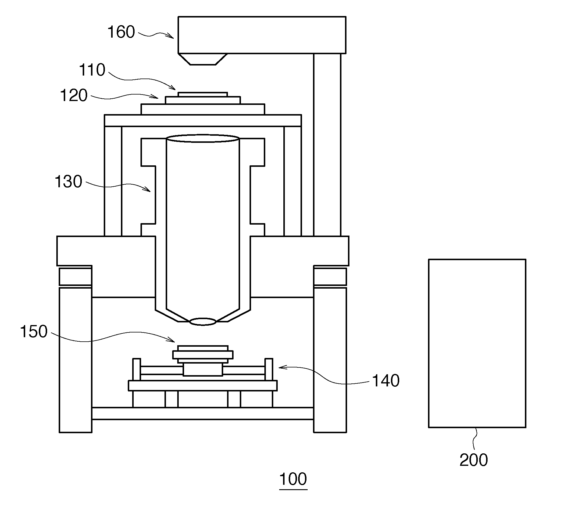
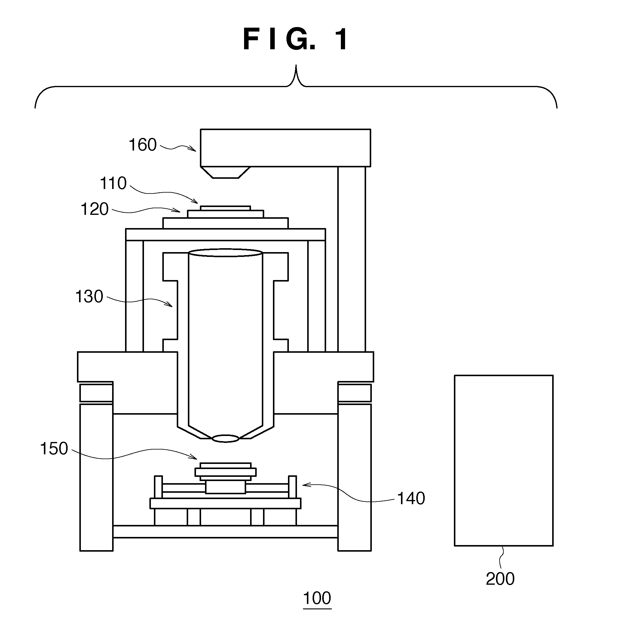
[0026]FIG. 1 is a view showing the schematic arrangement of an exposure apparatus according to a preferred embodiment of the present invention. An illumination optical system 160 illuminates a reticle (mask) 110 held by a reticle stage 120 with exposure light provided from a light source (not shown). A projection optical system 130 causes the exposure light transmitted through the reticle 110 to strike a wafer (substrate) 150 placed on a wafer stage 140, thereby forming an image of a pattern of the reticle 110 on the wafer 150. With this operation, the wafer 150 is exposed to light. As a light source, for example, a KrF laser or an ArF laser can be used.

[0027]In an exposure apparatus called a stepper, the reticle stage 120 stands still, and the wafer stage 140 stands still during exposure. When the exposure is complete, the wafer stage 140 is step-driven for exposure for the next shot. In an exposure apparatus called a scanning stepper, the reticle stage 120 and the wafer stage 140 ...

second embodiment

[0079]The second embodiment differs from the first embodiment in a control unit 50, more specifically the arrangement a regulating operation unit 56 of the control unit 50. More specifically, the second embodiment has an arrangement in which the control unit 50 shown in FIG. 6 is replaced with a control unit 50a shown in FIG. 7. The control unit 50a differs from the control unit 50 in that the regulating operation unit 56 (compensator 90) is replaced with a regulating operation unit 56a (compensator 90a). Note that things to which no reference is made can conform to the first embodiment.

[0080]In the second embodiment, the lag compensator 80 and the gain correcting unit 78 are arranged behind the adder 76. Operation in the lag compensator 80 and operation in the gain correcting unit 78 can be the same as those in the regulating operation unit 56.

[0081]According to the second embodiment, it is possible to accurately calculate the gain of the heat exchanger, which changes depending on ...

third embodiment

[0082]FIG. 8 is a graph showing the input / output characteristic of a control valve 34, that is, the relationship between the manipulated variable of the control valve 34 and the flow rate. In general, the input / output characteristic of the control valve is often not linear but nonlinear. Due to the nonlinear characteristic of the control valve, the gain represented by (Δ flow rate) / (Δ manipulated variable) changes. If, therefore, temperature regulation is performed without correction of the gain fluctuation of the control valve, the temperature stability will deteriorate.

[0083]The third embodiment differs from the first embodiment in the arrangement of the control unit. More specifically, the third embodiment has an arrangement in which the control unit 50 shown in FIG. 6 is replaced with a control unit 50b shown in FIG. 9. In this case, the control unit 50 differs from the control unit 50b in that the regulating operation unit 56 and the correcting operation unit 60 are replaced wi...


PUM


Abstract

A temperature regulating apparatus includes a correcting operation unit configured a) to calculates a heat exchange amount of a heat exchanger, a logarithmic mean temperature difference or an average temperature in the heat exchanger, and a flow rate of a second medium, b) to calculate an overall heat transfer coefficient of the heat exchanger based on the heat exchange amount, the logarithmic mean temperature difference or the average temperature, and the flow rate of the second medium, and c) to correct a gain of a regulating operation unit based on a change in the heat exchange amount with a change in the flow rate of the second medium supplied to the heat exchanger.

Description

BACKGROUND OF THE INVENTION[0001]1. Field of the Invention[0002]The present invention relates to a temperature regulating apparatus which regulates the temperature of a first medium by performing heat exchange between the first medium and a second medium via a heat exchanger, an exposure apparatus including the temperature regulating apparatus, and a method of manufacturing a device using the exposure apparatus.[0003]2. Description of the Related Art[0004]Recently, an exposure apparatus for manufacturing devices such as semiconductor devices has been required to have high productivity. Along with this requirement, the power consumption tends to increase. On the other hand, device patterns to be formed decrease in size more and more, and hence it is necessary to maintain the environment in the exposure apparatus more stably. With an increase in power consumption, in particular, a temperature regulating apparatus having high efficiency and very high temperature stability is required.[...

Claims


Application Information

Patent Timeline
Patent Type & Authority Applications(United States)
IPC IPC(8): G05D23/00
CPCF28F27/00G03F7/7085G03F7/70858H01L21/67248G05B13/024G05D23/2217G05D23/2424G05B11/42G05D23/1919G05D23/22G05D23/24
Inventor OKADA, YOSHIYUKI
Owner CANON KK
Why Eureka
Try Eureka