High density fiber optic acoustic array

a high-density fiber optic and acoustic array technology, applied in the field of high-density fiber optic acoustic arrays, can solve the problems of fbgs having to be specially packaged to limit their spectral sensitivity to changes in ambient temperature and pressure, sensor manufacturing is typically labor-intensive, etc., and achieves the effect of simplifying the hybrid wdm-tdm architecture of the sensor array and reducing costs

Inactive Publication Date: 2009-04-09
SABEUS
View PDF7 Cites 5 Cited by
  • Summary
  • Abstract
  • Description
  • Claims
  • Application Information

AI Technical Summary

Benefits of technology

[0015]In its broadest aspect, the present invention provides a method for simplifying the hybrid WDM-TDM architecture of a sensor array and reducing cost by minimizing the number of wavelengths used in a linear array of a fixed number of sensors. This is accomplished by forming FBGs having low reflectivity in the optical fiber and then coating the fiber to protect the FBGs such that they can be bent around a suitable mandrel or core without inappropriately adversely affecting the sensitivity of the array.
[0016]In another aspect, the present invention provides a method for altering the coating on an optical fiber incorporating FBGs to reduce the sensitivity of the optical fiber array to bending of the optical fiber, and to improve the acoustic performance of the fiber array by allowing the use of low reflectivity FBGs. In various aspects, the method includes thinning and recoating of the optical fiber in the area of the FBGs to achieve these improvements.
[0017]In another aspect, the method for improving the performance of a fiber optic grating used in an acoustic array includes removing an outer coating from a portion of an optical fiber having a fiber Bragg grating formed therein, and coating the portion of the optical fiber where the outer coating is removed with a non-voided plastic material. In another aspect, removing the outer coating includes dipping the portion of optical fiber in an acid, and in yet another aspect, the fiber is dipped into an acid bath where the acid is at an increased temperature, such as 100° C. In still another embodiment, the acid is sulfuric acid.

Problems solved by technology

However, two problems typically arise in the design of such arrays.
The first problem is that the FBGs must be specially packaged to limit their spectral sensitivity to changes in ambient temperature and pressure.
This limitation is important to ensure that the reflection spectra of the array remains coincident with the wavelengths of light emitted by the source laser.
Such sensors are typically labor intensive to manufacture, requiring manual splicing and packaging, including assembly of concentric mandrels and pressure sealing of the sensors, and the like.
The second problem with such sensors is that due to limited optical power availability, optical crosstalk between sensors and high optical configuration and transmission losses, FBGs with reflectivities on the order of 1-5% are used as interferometer reflectors in acoustic sensor arrays.
However, the use of such FBGs results in being able to incorporate very limited numbers of sensors per fiber per wavelength.
Such systems are typically limited to including 1-4 sensors, and rarely are they able to include more than 6 sensors without experiencing significant loss of sensitivity due to crosstalk which results from multiple reflections that limit array gain an degrade narrow band array processing results.
However, if the FBG reflectivity is limited to approximately 0.05%, this number quickly increases up to 24 with nw>3. This greatly simplifies optical architecture requirements, and consequently labor costs associated with array assembly.
This magnitude of sensitivity loss can cause the FBG to be unusable for interferometric sensing applications, where the interrogating laser must have a wavelength near the center of the FBG reflection spectrum, and where the array is exposed to temperatures ranging from 0-35° C. and hydrostatic pressures from approximately 15 to 400 psi.
However, the cost of the associated packaging materials, labor and space can be significant.

Method used


Image

  • High density fiber optic acoustic array
  • High density fiber optic acoustic array
  • High density fiber optic acoustic array

Examples


Embodiment Construction

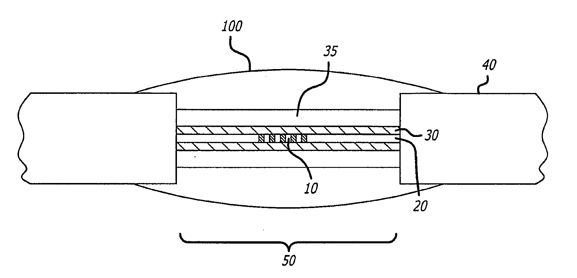
[0026]Referring now to the drawings in detail, in which like reference numerals indicate like or corresponding elements among the several figures, in a presently preferred embodiment, an optical fiber that is intended for use in an acoustic array is coated with a plastic material that is foamed to enhance the acoustic sensitivity of the fiber using an extrusion process which allows very long lengths of fibers, on the order of kilometers, to be coated in a rapid, low cost process. This process, however, results in an optical sensor array that has unsuitable sensitivity to changes in pressure, temperature or bending, that is stressing, of the fiber.

[0027]Simply removing all of the coating in the vicinity of the FBGs forming the sensor array incorporated into the optical fiber reduces the magnitude of the aforementioned sensitivities, but presents several problems. First, the thick plastic material that is typically used to coat the optical fiber is difficult to remove from the optical...


PUM

PropertyMeasurementUnit
reflectivityaaaaaaaaaa
wavelengthsaaaaaaaaaa
temperatureaaaaaaaaaa

Abstract

A method for optimizing the architecture of a linear sensor array using WDM-TDM technology and stabilizing the reflectivity spectral profile of the fiber Bragg gratings of the sensors against the influence of environmental factors such as pressure and temperature is provided. The method includes stripping a portion of the foamed coating on the exterior of an optical fiber in the region of the fiber Bragg grating to thin the coating in the region of the grating. After the coating is stripped and the optical fiber cleaned, the area of stripped fiber is recoated with an unvoided plastic.

Description

BACKGROUND OF THE INVENTION[0001]Arrays of fiber optic sensors are used for acoustic sensing within such applications as marine surveillance and perimeter security. Because of the high sensitivity and dynamic range typically required for these applications, interferometric sensors are often the optical instruments of choice. Fiber Bragg Gratings (FBGs) are widely used to provide the optical reflections within the interferometers, especially in the recently developed simplified low-cost single line array architecture, as shown in Kirkendall et al., Progress in Fiber Optic Acoustic and Seismic Sensing, Proceedings of the 18th Optical Fiber Sensor Conference, Cancun, Mexico, October 2006, the subject matter of which incorporated by reference herein in its entirety.[0002]As a general rule, improved performance of such a single line array system is obtained by adding more sensors to the system. Within towed arrays, including more sensors enables increased acoustic bandwidth and / or array ...

Claims


Application Information

Patent Timeline
Patent Type & Authority Applications(United States)
IPC IPC(8): G02B6/02G02B6/00
CPCG01H9/004G02B6/02104G02B6/0219G02B6/02171G02B6/02185G02B6/02123
Inventor GOLDNER, ERIC LEELAM, LEOMARTIN, GRAHAMRYU, KEVIN
Owner SABEUS
Why Eureka
Try Eureka